PLC code utilization related research, PLC code defect classification
The main point of this article
1, PLC code utilization related research
2, PLC code defect classification: PLC code logic defects, PLC code security requirements specification
3. Formal Analysis and Verification of PLC Codes: Difficulty in PLC Formal Analysis, Formal Analysis of PLC Codes
With the industrial control system from closed to interconnected, a large number of controllers are equipped with Ethernet communication components, allowing an attacker to directly access the PLC hardware and its programming software. However, the logic control layer of the PLC lacks protective measures such as authentication and monitoring, and the PLC code's security flaws become one of the important security threats of industrial control systems.
The first part of the PLC code utilization related research
As with traditional programming languages, PLCs have code security flaws that leave the back door for attackers attacking industrial control systems.
In 2013, Sidney of South Carolina University conducted an in-depth study on PLC code design security flaws, and classified PLC code design level defects into two types based on hardware defects and software defects. The attacker can use PLC code defect to destroy code logic, perform intermediate code instrumentation, implement arbitrary code execution and so on.
In 2014, Beijing University of Science and Technology Li Weize proposed and analyzed a new kind of cyber physical attacks against SCADA systems - pseudo-logical attacks.
In the blackhat-US conference in 2015, Klick and others injected a new type of back door into the Siemens S7-300. Through the injection tool, the SOCK5 proxy function was implemented for SNMP scanning on the S7-300. The author used the security flaw of the jump instruction in the PLC program to successfully embed malicious instructions in front of the main program OB1 so as to control the start and stop of the PLC and output registers.
In November 2016, Ali Abbasi and others at the blackhat Europe conference realized a new attack on the PLC input/output interface. This attack changed the system's operation logic by falsifying the input and output pins.
In March 2017, scholars from Hyderabad, India and Singapore demonstrated the PLC Ladder Logic Bombs (LLBs) for industrial control systems. The logic bomb is malicious software written in ladder language. This malware can be injected into the PLC's existing control logic by changing the control action or waiting for a specific trigger signal to activate malicious behavior in order to achieve sensor data tampering. System sensitive information acquisition and PLC denial of service attacks.
The second part of PLC code defect classification
Unlike traditional IT systems, industrial control systems have their own special programming languages. According to the Industrial Control Programming Language Standard (IEC 61131-3) developed by the International Electrotechnical Commission, PLC programming languages ​​include the following five: Ladder Logic Languages ,LD), Instruction List (IL), Function Block Diagram (FBD), Sequential function chart (SFC), and Structured text (ST). The code defect study in this article is also based on the above programming language.
Although the intrusion of industrial control systems is similar to that of traditional Internet intrusions, the deployment of industrial control systems is closely coupled with the physical process flow. Therefore, the use of code logic defects in process flow has become one of the effective countermeasures against industrial control systems, such as traps. Gates, logic bombs, Trojan horses, worms, Zombie, etc., and this new type of malicious code is more powerful and destructive. This article mainly studies the PLC-based software code defects, and classifies the PLC code defects from two aspects of code logic defects and violation of security requirements specification.
(A) PLC code logic defect
The PLC code logic defect has the characteristics of strong concealment, it is hard to find, and it can lurk for many years. The traditional security defense ideas cannot solve this problem. In an industrial control system, one switching action is not performed, the process execution flow changes, and the specific output response failure may cause devastating damage.
This article uses the ladder diagram language as an example to analyze the PLC code logic defect, the ladder diagram language image is intuitive, and the relay control circuit expression pattern is very similar. Ladder diagrams consist of graphical symbols such as contacts and coils combined with instruction symbols such as numeric instructions, arithmetic instructions, and control instructions. Logic defects in PLC code are also caused by improper placement of these elements and component locations, incorrect links, and ranges. Table 1 shows the PLC code logic defect classification and its related description.
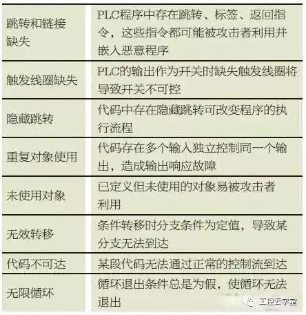
Table 1 PLC code logic defect classification table
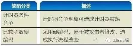
By exploiting the logic defects of the PLC code listed in Table 1, denial of service attacks, man-in-the-middle attacks, and changes to the normal workflow of the controller can cause incalculable losses to the industrial control system. Several PLC code defect analysis and utilization are given below.
(1) Timer condition competition defect
The timer in PLC programming can trigger the timer by setting a preset time. Improper placement of the timer's completion bit element may cause the process involving the completion of the timer bit and the timer itself to enter a race condition. When the timer complete bit becomes a necessary element to activate its own trigger mechanism, this race condition occurs causing the timer to fall into an infinite loop and reset the timer.
As shown in FIG. 1 , the preset value of the timer is set to 0, so that the timer trigger bit and the timer are turned on at the same time, causing the timer to continue to oscillate, so that the output O4.1 cannot be triggered, resulting in a wrong sequence or process flow of the program. Failed to shut down such failures and achieve denial of service attacks.
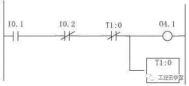
Figure 1 Timer conditional competition defect ladder
(2) Comparison function hard coding defects
The digital instructions in the PLC logic code include a comparison instruction. If the comparison instruction is incorrectly coded, it may cause a security risk, and a malicious user may insert incorrect data into the process through a comparison instruction. This data may cause the process sequence to change, or cause the process to be aborted completely.
As shown in Fig. 2, assume that the normally open contact I0.1 can trigger the initialization of the high pressure boiler, connect a comparison function after the normally open contact, and O4.1 controls the shutdown process of the high pressure boiler. When the value of A is greater than or equal to the value of B, O4.1 is activated and the boiler stops heating. If the comparative element B is hard-coded using a fixed value without reference to the values ​​in the symbol table, the data in B is not protected. By increasing the temperature value of B, the high-pressure boiler is continuously heated until the equipment is damaged or even exploded.

Figure 2 Comparison function defect ladder
(3) Jump and link defects
Jump and link defects are caused by some jump instructions that can affect the order of program execution and error jumps of logic block instructions to a program segment. This type of code defect is similar to a man-in-the-middle attack. An attacker can jump to an unexpected location with a bad jump instruction and insert a malicious program segment at an unexpected location and return it to the location before the jump. .
Figure 3 shows the code utilization method based on jump and link defects. We can use jump to the subroutine JSR function to jump from File1 to the malicious code file File3, introduce the malicious subroutine and return to the position before the JSR jump. , complete the insertion of malicious code to achieve man-in-the-middle attacks.
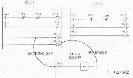
Figure 3 Jump and link defect map
(B) PLC code security requirements specification
In addition to the PLC code logic defect, the security requirement attribute of the PLC code at the physical site will also determine the success or failure of the PLC defect utilization. The security requirement attribute is determined by the security requirements of the industrial control site. It refers to the constraint of the state, timing, time, input and output of the device in order to ensure the safety of the industrial control system. For example, the rated speed of a motor does not exceed 2000 rpm and the green light at the intersection cannot be lit at the same time. In the code may be due to the programmer's negligence caused by the violation of the security requirements attribute, you need to detect it. It can be seen that the security requirement attribute is not a constant, and it needs the actual user to describe and input it into the detector. Pavlovic constrains the PLC's safety requirements such as device status, timing, time, and input/output. This article summarizes the security requirements into the following five categories, as shown in Table 2.
Table 2 PLC code security requirements specification table

Part III Formal Analysis and Verification of PLC Codes
The PLC code uses the "sequential scan, continuous cycle" mode of operation. The typical PLC work process includes three different stages: reading input data into memory, processing data in memory, and updating output data. PLC program only contains a limited set of states and limited variables, and the program does not contain loops, security requirements depend on the output variables, so to a certain extent formal verification techniques are suitable for PLC program security analysis and malicious code detection.
Formal analysis is divided into two theorem proving and model checking methods. The theorem proving process is too complicated and tedious. In fact, the theorem proves that the verification of the correctness of PLC program is not recognized. Model checking is a widely used formal method. It is more suitable for the verification of PLC code. It is easier to model low-level PLC programs than traditional computer programs because his state transition system is relatively simple.
(I) Difficulty in Formal Analysis of PLC
(1) PLC lacks high-level programming language
PLC programming belongs to low-level programming languages ​​and has many programming languages, grammatical semantics are obscure, hierarchical addressing, address addressing is complex, implicit type data exists, modeling is difficult, and language attributes are easily lost.
(2) Missing time modeling
The real-time nature of the industrial control system is very demanding. Therefore, modeling time is extremely important. The object of time modeling should include the cumulative time of the timer, the running time of a single instruction, and the execution cycle time, since the timer is a cyclical cycle. Global variables, taking time into account when modeling can greatly increase the difficulty of modeling and increase the time of detection, but can not detect time-related safety specifications without considering time.
(3) The lack of physical environment modeling
The industrial control system is closely related to the physical environment. The input of the industrial controller can generally be considered as the output of the physical environment, and the output can generally be considered as the input of the physical environment, forming a closed-loop loop. The industrial controller cannot be accurately simulated without considering the physical environment. the behavior of.
(4) State space explosion
The PLC code contains many variables and the state space is large. Modeling and analyzing the PLC code is based on the state transformation. If the model detection is performed directly, the state space will be exploded.
(II) Formal analysis of PLC code
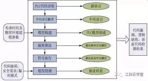
The formal verification of PLC code aims to detect PLC code defects and prevent the invasion of malicious code. At present, the research of discovering PLC code defects through formal verification methods mainly focuses on the study of PLC code formal model construction, PLC code defect and safety requirement specification, and PLC code model detection technology, as shown in Figure 4.
(III) Technical Route of PLC Control Code Detection
(1) Intermediate language translation
Since industrial controllers support multiple standard programming languages ​​and have large differences in syntax and semantics, the existing model detection technologies are mostly based on specific programming languages. In order to reduce the complexity of modeling, we need to translate the PLC programming language into An intermediate language that the model detector can handle.
Darvas et al. proposed to convert the SCL language of PLC program into the NuSMV-based intermediate model method, which is an intermediate model that is close to the automaton model. McLaughlin et al. presented the method of translating the PLC instruction language IL language code into the Vine-based intermediate language ILIL. Zonouz et al. transformed MC7code to ILIL through decompilation. The ILIL is also described using the BitBlaze binary analysis tool Vine plugin.
(2) Time Model Construction
The real-time requirements of industrial control systems are very high, so time is an important modeling object. The On-Delay Timer (TON) is used to ensure the real-time property in the PLC. The TON instruction provides the delay mechanism for the PLC input signal. Modeling the TON timer greatly increases the difficulty of modeling and increases the time for detection, but it does not detect time-related safety specifications without considering time. Therefore, the formal verification of the TON timer becomes one of the bottlenecks in formal verification of the PLC code.
In recent years, there have been some modeling studies on TON timers. Masder et al. started this research first. They converted the IL program into a timed automaton model and used an automaton and a Prometa model to model the timer. Willems uses a time machine to model the TON model to solve problems with TON. Wan et al. formally verified the TON timer against the ladder diagram language in the theorem proving device Coq, but did not give a formal description of the general-purpose module PLC program. Sidi formalized the TON timer against the instruction list language in the theorem prover Coq.
(3) Model Detection Technology
Model detection is a widely used automated verification technology. The appropriate model is selected to verify the system, and the required attributes to be verified are checked by systematically probing the model. Because model checking can be performed automatically, and can provide a counterexample path when the system does not meet the nature, it is more respected in the industry than deductive proof. Model checking is particularly useful for verifying the safety of a PLC system because it is easier to model low-level PLC code as a state transition system than traditional computer programming.
There are many model detection tools used in the current research, such as SMV, UPPAAL, SPIN and so on. Yoo et al. used a Verilog model and a CadenceSMV model to perform model checking on the PLC code of the nuclear power plant control system. McLaughlin et al. developed a TSV
(Trusted Safety Verifier) ​​tool, which uses the Temporal Execution Graph (TEG) diagram to perform model checking. The original IL code assigns values ​​to output variables and then converts them to ILII intermediate language. According to the security requirements given, TSV uses the generated The TEG diagram determines the specific atomic proposition value. Zonouz et al. also used the TEG diagram method to detect the model, first invert the linear temporal logic specification formula to obtain the TEG-UR diagram model P, and then searched for the satisfied path in the model M. Finally, if in the third step, If there are any paths, the original code can be considered to meet security requirements and can be safely executed. If there is a path, the corresponding counterexample can be obtained by violating the path condition of the constraint.
The actual development of the PLC program contains multiple variables and state space, and the execution path is complicated. You will encounter a problem with the explosion of the state space. The most effective way to solve the state space explosion problem is symbolic execution. McLaughlin et al. propose a state aggregation method that combines inputs with the same output to avoid the generation of equivalent states. Guo et al. proposed a symbolic execution tool SymPLC for automatic test of PLC programming language. SymPLC takes the PLC source code as input and converts it to C language before the application symbol is executed, overwriting all paths in each cycle task with the system's generated test input. To this end, they proposed some PLC-specific reduction techniques for identifying and eliminating redundancy.
In industrial control systems, a small code defect may affect the entire industrial process and even threaten the safety of life and property. This paper focuses on the study of code control security in industrial control systems. It classifies industrial control code defects from two aspects of PLC code logic defects and code security requirements specification, and combines the common ladder logic defects in reality to construct a code utilization scenario. These code logic defects implement denial of service attacks on industrial control systems, man-in-the-middle attacks, and so on. Formal verification of PLC code is an important and effective way to discover the defects of PLC code. The article finally focuses on how to implement, and briefly describes the formal verification of PLC code from three aspects: intermediate language translation, time model construction and model detection technology. Technical line and research progress.
Shenzhen Xcool Vapor Technology Co.,Ltd , https://www.szxcoolvape.com