Research on Classification of Ultrasonic Bottle Thickness Detection Based on FPGA
At present, the non-contact liquid testing equipment used often has false alarms, which can easily cause disputes between passengers and security personnel, and affect the security order of airports and public places. In particular, the probability of underreporting cannot be ignored, causing great security risks. Therefore, liquid non-contact security inspection equipment is now difficult to meet the requirements of practical use.
The reasons for the inability to use liquid non-contact security equipment are diverse. The effect of liquid-filled containers (mostly bottle-shaped containers) on liquid non-contact detection is enormous and cannot be ignored. Experiments show that the material and thickness of a bottle have a great influence on the false alarm probability and false negative probability of liquid non-contact detection. Therefore, how to accurately classify and measure the material of the bottle has become the focus of attention at present.
Ultrasonic waves are sound waves with a frequency above 20KHz. Ultrasonic waves are shorter than normal sound waves, have good directivity, and can penetrate transparent and opaque substances. They are widely used in metal flaw detection, distance measurement, thickness measurement, and in the ocean. The fields of exploration and development, non-destructive testing and evaluation, and medical diagnosis play an irreplaceable role. Ultrasonic testing technology (UT) is one of the five most commonly used detection techniques. Ultrasonic bottle material classification and thickness measurement are one type of ultrasonic testing. It has the characteristics of low cost, convenient use, high speed, harmless to the human body and easy to use on site. Therefore, it is a non-destructive thickness measurement technology that develops faster. Ultrasonic bottle material classification and thickness measurement is a non-contact detection technology, which is not affected by light and the color of the object to be measured. It is more hygienic than other instruments, and is more resistant to humidity, dust, high temperature, corrosive gas and other harsh environments. Maintenance, non-polluting, high reliability, long life and so on.
In addition, the related detection of ultrasonic bottles is widely used in many fields such as environmental monitoring and food safety.
Development review:At present, the domestic ultrasonic thickness measurement technology is developing rapidly. In the late 1960s, the domestic electronic tube eddy current thickness gauge was available. With the development of new industrial materials, microelectronics technology application and standardization business process, especially in the past ten years, the thickness measurement technology has developed rapidly, the thickness gauge is in circuit design, the new sensor application, the multi-standard and versatility of the probe, the quantity Value display and data printing, measurement and control function expansion and intelligent aspects, continue to make breakthroughs and innovations. The development of these technologies has promoted the continuous maturity of ultrasonic thickness measuring instruments. It is used in navigation, aerospace, automobile manufacturing and other industries due to its small size, light weight, simple operation, low surface finish of the object to be tested, and large measuring range. Great economic and social benefits have come, and they have been valued and applied in major industrial countries around the world.
However, the latest API.5C standard requires rapid and continuous measurement of wall thickness. For a long time, many domestic and foreign research institutions and related personnel have been working on this research, but the results are not satisfactory, and the ultrasonic classification technology for materials remains At the research stage, its specific practical application has not been reported.
Project development content:The project focuses on how to classify bottle materials and how to measure bottle thickness. The ultrasonic transmitting probe and the ultrasonic receiving probe are the main sensors of the project, and complete the transmission of the ultrasonic wave and the detection of the echo; then the A/D conversion of the relevant signal, the low-pass denoising process; the denoised signal Firstly, the autocorrelation theory of the signal is applied to accurately extract the delay of the transmitted and received signals. At the same time, we also obtain the spectrum of the echo signal through the FFT and the attenuation information of the transmitted and received signals through the amplitude extraction module; Echo spectrum information, delay of transmitting and receiving signals, and attenuation of transmitting and receiving signals are analyzed by a unified logic to obtain four-point input information of artificial neural network. Using the obtained four-point input information, we adopt artificial neural network algorithm and pass Offline learning builds a way to classify the bottle material; finally we can complete a bottle thickness measurement function that automatically identifies the bottle material.
Project innovation : Using a large number of efficient algorithms, a high-precision, fast-speed thickness measurement system was designed. At the same time, an artificial neural network was used to train a system that can automatically identify the bottle material (plastic, glass, ceramic).
Basic requirements of the project:
Measurable materials plastic, glass, ceramic
Probe frequency 5Mhz
Measurement accuracy 1%* thickness value 0.05mm
Use environment -10~60 (degrees Celsius)
two. Project preliminary plan introduction1. Introduction to the overall plan of the project development
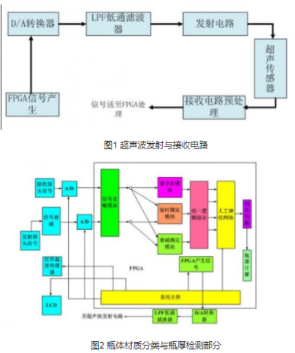
1.1 Ultrasonic transmitting and receiving circuits, as shown in Figure 1:
Transmitting circuit
The transmitting circuit generates a high voltage (above 300 volts) spike signal that excites the ultrasonic ultrasonic sensor. The input signal of the pulse generator is generated by the FPGA. This scheme uses a non-resonant transmitting circuit, as shown in Figure 3:
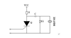
Figure 3 Transmitting circuit
The working principle of the non-resonant transmitting circuit is that when the thyristor (or thyristor) is turned on, the capacitor C is discharged to generate a short pulse, which excites the piezoelectric ceramic lens in the probe to emit an ultrasonic pulse. In the design, it is necessary to consider the thickness of the pulse signal, that is, the number of consecutively transmitted pulses, which has an important influence on the accuracy of the measuring instrument. The larger the thickness, the larger the transmission power, the larger the tailing signal of the transmitted wave, and the larger the corresponding measurement dead zone. Conversely, the smaller the blind spot is measured. However, when the transmission power is small, the echo signal is not obvious, which also affects the detection result.
Receiving circuit
The amplitude of the echo signal received by the ultrasonic probe is very small. When the background noise is serious, the amplitude of the number may be almost equal to the amplitude of the noise, or even submerged in the noise. If effective signal extraction techniques are not used to suppress the effects of interference, measurements cannot be made. To ensure the success of the measurement, appropriate means must be used to enhance the signal and eliminate the effects of noise. The receiving circuit is composed of an amplifying circuit (three stages), a detecting circuit, a comparing circuit, etc., as shown in FIG. 4:
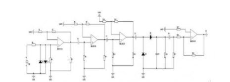
Figure 4 Receive amplifier circuit
After the single probe is measured, the transmitting and receiving probes are integrated together, and a high emission voltage is directly applied to the input end of the receiving circuit. In order to ensure the normal operation of the operational amplifier, and the higher voltage makes the lens more penetrating. Ultrasound signal. Add two diodes D1 and D2 to the front end of the op amp to form a clamp circuit, so that the transient signal when the sensor is excited passes through D1. The clamp circuit composed of D2 is limited to ±0.7V, which is the high voltage signal input to the pre-amplifier. Clamp is obtained. For small signals, because the difference between the potential at point a and the potential at point b is small, the switching diode is directly input to the operational amplifier by the cutoff micro-signal, so that the input of the operational amplifier is clipped to protect the operational amplifier. effect.
1.2 Bottle material classification and bottle thickness detection, as shown in Figure 2:
Signal denoising function block, which is mainly used for denoising processing of transceiving signals. It mainly consists of two 64-stage low-pass filter modules, which implement our improved DA algorithm.
The spectral analysis function block is mainly used to perform Fourier spectrum analysis on the received probe signal. It mainly includes the FFT module, and its implementation we call the FFT IP Core.
The delay measurement function block mainly uses the autocorrelation of the signal to determine the delay of the transmitted and received signals. Compared with the MCU to extract the delay information, the reference autocorrelation algorithm has the characteristics of accurate extraction delay. It mainly includes a convolution module and a threshold comparison module.
Attenuation measurement function block, which mainly measures the amplitude attenuation of the transmitted and received signals. It mainly includes amplitude extraction module, timing information control module and divider module.
The bottle classification function block is designed to create a classification system that can distinguish three bottle materials (ceramic, glass, plastic) through offline learning. It mainly includes artificial neural network module and decision circuit module.
The bottle thickness calculation function block requires the temperature value of the infrared temperature sensor and the result of classification of the bottle material as a priori condition, and then calculates the thickness of the bottle body by using the relevant formula of the thickness calculation. It mainly includes a thickness calculation module.
The system master function block, which completes the timing control of the peripherals of the entire system. It mainly includes 2 A/D controls, infrared temperature sensor control, LCD control, and ultrasonic master logic control.
2. Key module implementation algorithm introduction2.1 Introduction to Bit String Distribution Processing Algorithm (DA Algorithm)
The DA algorithm is an abbreviation of the distributed arithmeTIc algorithm. Chinese translated into distributed algorithms. The implementation of the wavelet filter is implemented using a distributed algorithm. As a digital signal processing algorithm, distributed algorithm is widely used to calculate product and operation. Compared with traditional product and structure, DA algorithm has the efficiency of parallel processing. If a distributed algorithm is used to implement the wavelet filter, its working speed in the FPGA is only related to the width B of the input data, and is independent of the order N of the filter. The order only affects the usage of the FPGA resources.
The distributed algorithm of bit string distribution starts from the lowest bit, combines the lowest bits of all input data together as the address of the table lookup, addresses the lookup table, and obtains a result after looking up the table, and then The result of the lookup table is added or subtracted from the register value shifted by one bit, and the result of the operation is placed in the register, and then all the lower bits of the input data start to address the lookup table to obtain another result of the table lookup, The result is added to the result of the register that is shifted to the right by one bit, that is, the result stored in the register, and so on, until all the bits are completed. It is important to note that for signed numbers, the value obtained after a table lookup operation at the highest bit should be subtracted from the result of a register shifted to the right by one bit, and the negative number is expressed in the form of a complement.
The basic structure of the bit string distribution multiplier is shown in Figure 5:
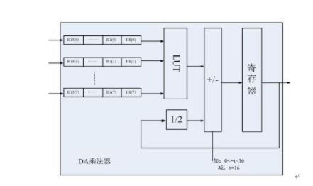
Figure 5: Filter structure of the string distribution
The DA algorithm in this project is mainly applied to the multiplier design of artificial neural network and FRI digital filter.
(1) Introduction to the improved distributed processing algorithm to implement FIR digital filter
First, we study the feasibility of the serial distributed algorithm, to achieve an 18-bit 64-order FIR high-order distributed filter, the size of the occupied resources is related to the order K of the digital filter. When K = 64, the FIR digital filter needs to store at least 264 units of values, and when creating a lookup table, it is necessary to establish 264 numbers for use in the lookup. The scale of these numbers is quite large. If the FPGA memory resources cannot be satisfied directly on the FPGA chip, on the other hand, it is necessary to establish a 264-number lookup table, and the workload is very large. When the bit width is 18, the FIR filter of the full serial distributed algorithm needs to perform 18 shift additions when calculating a filtering result, so that the operation speed is slow and cannot meet the real-time requirement. Even with the introduction of pipeline technology, the FIR digital filter of the full serial distributed algorithm is not very fast, and the resource consumption of the lookup table is still huge. Although the performance of FPGAs has been greatly improved, the 18-bit 64-order FIR digital filter implemented by the full-serial distributed algorithm still cannot meet the requirements of resources and computing speed.
In this case, we have improved two aspects of the distributed processing algorithm:
The entire FIR digital filter is divided into cascades of several FIR sub-filters, so that the resource usage of the look-up table of each sub-filter is reduced, and the amount of work required to create a look-up table is also reduced. Its structure is shown in Figure 6:
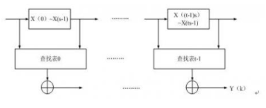
Figure 6 Schematic diagram of high-order filter decomposition into low-order filters
The input data bit width of the FIR digital filter determines the number of shift addition operations. In order to increase the operation speed of the FIR digital filter, the bit width of the input data can be divided into the bit widths of the L bits of the m segment, and the m segments are The decomposed number is simultaneously searched, which can improve the speed of data calculation. Its structure is shown in Figure 7:

Figure 7 Schematic diagram of the data bit segmentation FIR filter
If we improve these two aspects of the DA algorithm at the same time, we propose an improved DA algorithm. At the same time, we propose an implementation scheme of a 64-order low-pass filter based on the improved DA algorithm.
The improved DA algorithm in this project is mainly applied to the design of 64-stage low-pass filter. Its structure is shown in Figure 8:
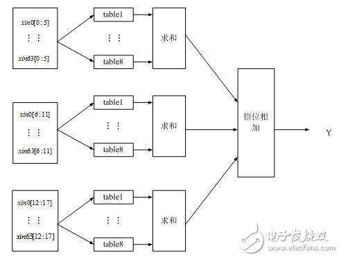
Figure 8 Implementation of 128-order low-pass filter based on improved DA algorithm
(2) Introduction to artificial neural network algorithm
Artificial neural network (ANN) is a computational structure that simulates biological processes based on modern neurobiology research to reflect certain characteristics of the human brain. It is not a true description of the human brain, but just some sort of abstraction, simplification and simulation. Neurons and their synapses are the basic devices of neural networks. Therefore, the simulated biological neural network should first simulate biological neurons. In artificial neural networks, neurons are often referred to as "processing units." Sometimes it is often referred to as a "node" from a network perspective. Artificial neurons are a formal description of biological neurons. They abstract the information processing process of biological neurons and describe them in mathematical language. They simulate the structure and function of biological neurons and express them with models.
To simulate biological neurons, a simplified artificial neuron is shown in Figure 9. The neuron is a multi-input, single-output, nonlinear component.
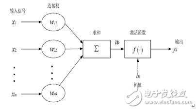
Figure 9 simplified neuron model
An artificial neuron model can be thought of as consisting of three basic elements:
A set of connection weights (corresponding to synapses of biological neurons), the connection strength is represented by the weights on each connection, the weight is positive for excitation, and the negative is for inhibition.
A summation unit for determining the weighted sum (linear combination) of each input information.
A nonlinear activation function that acts as a nonlinear map and limits the neuron output amplitude to within a certain range. There is also a threshold. The threshold is also considered to be an input component, ie the threshold is also a weight. In the design of the network, the deviation plays an important role, which makes the graphics of the activation function move left and right and increases the possibility of solving the problem.
The so-called artificial neural network structure mainly refers to its connection mode. From the perspective of topology, the neural network belongs to a graph in which neurons are nodes and edges are connected as edges. From the perspective of connection methods, there are two main types, namely, feedforward neural network and feedback network. After the topology of a neural network is determined, in order to make it have certain intelligent characteristics, it must have a corresponding learning method to cooperate with it. How to set the weight is an important feature to distinguish different artificial neural network learning algorithms. The learning of artificial neural networks can generally be divided into two types, namely, supervised learning (with teacher learning) and unsupervised learning (without teacher learning).
The artificial neural network of this project is designed as a two-stage artificial neural network, in which the structure of the first-level internal neural network is shown in Figure 10; the structural block diagram of the secondary artificial neural network is shown in Figure 11:
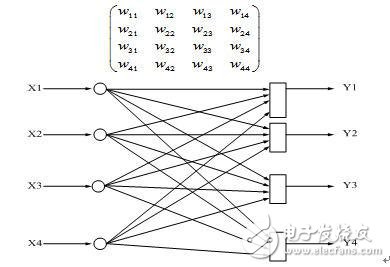
Figure 10 Schematic diagram of the internal neural network
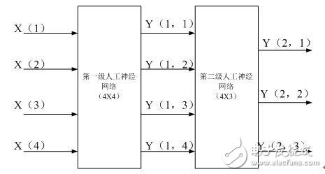
Figure 11 Block diagram of the secondary artificial neural network
According to the basic characteristics of the artificial neural network, we use the form of multiplier package to implement the basic implementation. The implementation method is shown in Figure 12:
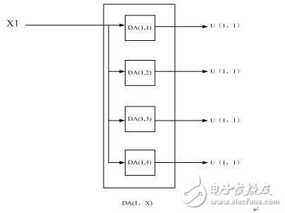
Figure 12 Multiplier package
Then the FPGA implementation of the primary neural network is shown in Figure 13:
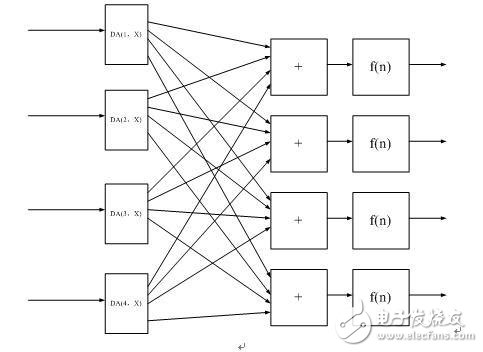
Figure 13 FPGA implementation of a first-level artificial neural network
Introduction to CORDIC calculation special function algorithmIf we use FPGA to implement some kind of digital signal processing algorithm, and the algorithm uses a non-ordinary (transcendental) algebraic function, we can use Taylor series to approximate this function.
This problem is reduced to a series of multiplications and additions. A more efficient method to consider is the algorithm based on Coordinate RotaTIon Digital Computer (CORDIC). The CORDIC algorithm is based on numerous applications such as adaptive filters, FFT, DCT, and neural networks.
The officially defined CORDIC algorithm is as follows:
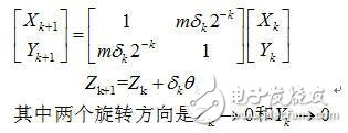
Two basic structures can be implemented to implement the CORDIC structure: a simpler state machine and a high-speed full-flow processor.
2.3 Introduction to Restoring Algorithm
The Restoring algorithm is a linear convergence division algorithm. Its main idea is to first adjust the denominator and load the numerator into the remainder register, then subtract the adjusted denominator from the remainder and store the result in the remainder register. If the new remainder is positive, we will add 1 to the quotient, otherwise the quotient will not Change and also need to restore the former residual value by adding the denominator. We can use the design structure of the state machine to realize the idea of ​​this division algorithm.
The Restoring algorithm in this project is mainly applied to the design of the divider in the amplitude attenuation module.
2.4 Introduction to the piecewise function algorithm
The piecewise function is a function that has different corresponding ranges for the different values ​​of the independent variables. The implementation of the segmentation function has the characteristics of low resource consumption and fast processing speed. For example, a piecewise function containing a second-order nonlinear function, as shown in the following equation:
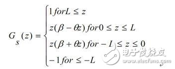
For the implementation of second-order nonlinear functions, as shown in Figure 15:
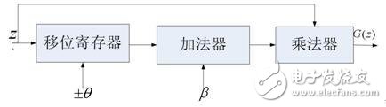
Figure 15 Implementation of second-order nonlinear functions
The segmentation function in this project is mainly applied to: the activation function in the artificial neural network.
The design of f(n).
3. Project design refinement module solution
The block diagram of the project design refinement module is shown in Figure 16:
The design difficulties of this project:
(1) The design of the autocorrelation module that accurately measures the delay information, because the autocorrelation information has a great influence on the amplitude extraction of the transmitted and received signals.
(2) The design of an efficient 64-order filter is designed to design a low-pass filter that saves both hardware resources and efficient real-time output.
(3) The design of an artificial neural network that can be accurately classified requires a large amount of discrete learning and an accurate topology.
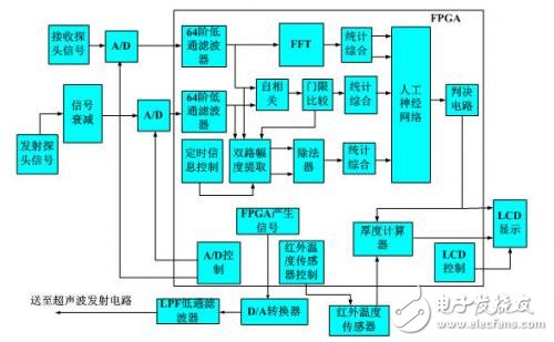
Figure 16 Project design refinement module block diagram
Shenzhen Happybate Trading Co.,LTD , https://www.happybateprojector.com