Using PIN diodes to solve broadband RF switching problems
Expensive mechanical switches for precision test instruments, such as vector network analyzers, have proven to be appropriate. However, for mass-produced consumer products, such as cable or satellite TV (CATV/SATV) transmission systems, lower cost electronic switches are more appropriate. Such switches are based on transistors or PIN diodes. Semiconductor switches have no moving parts, so they have faster response times and longer life spans than mechanical switches.
PIN diodes are commonly used in switching units for single-pole, single-throw (SPST) and single-pole, multi-throw switches. The PIN diode acts as a flow control resistor for signals with frequencies above 10 times the diode cutoff frequency (fc).
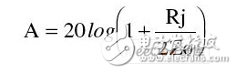
Coupled with a forward bias current, the PIN diode junction resistor Rj can be changed from high impedance to low resistance. In addition, the PIN diode can be used in both the series switching mode and the parallel switching mode. The insertion loss A of the series switch is:
When connected in parallel, the insertion loss becomes:
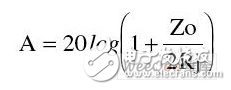
Here Zo is the characteristic impedance (typically 50 or 75 Ω in RF transmission systems).
The topology of the selector switch requires a trade-off between bandwidth and isolation requirements. Although series switches have the advantage of transmitting low losses over a wide frequency range, they are less isolated. Parallel switches are typically used in conjunction with 1/4 wavelength transmission lines, which are essentially narrowbands, but these transmission lines have higher isolation than series.
Both test instruments and CATV/SATV equipment require RF switches with multiple octaves of operation and do not produce significant signal loss. A multi-carrier environment similar to CATV/SATV has strict linearity requirements for switches. It also does not introduce excessive distortion that causes inter-channel interference, which can cause signal degradation.
To improve the isolation of a single PIN diode, two or more PIN diodes can be used in series mode. This series connection and 蔼 allow sharing the same bias current to save power. The advantage of double-ended switching components, such as PIN diodes, is that they can be easily cascaded in series with external diodes. In contrast, three-terminal transistors require the same control circuitry for each additional series switch component.
Body effect diode and epitaxial growth type PIN diode
Circuit designers need to distinguish between the type of body effect and the epitaxial growth (Epi) PIN diode. These two different methods of constructing PIN diodes result in significant differences in their respective RF performance, thus affecting the suitability of the PIN diode for various applications. Body-effect diode substrates have a low doping density and require a high bias current for conduction. Therefore, body-effect PIN diodes are generally not suitable for portable and other battery-related applications. Its very thick and pure intrinsic (I) layer results in a long carrier lifetime in the range of 300 to 3,000 ns. This long carrier lifetime is a fundamental parameter that guarantees low distortion performance in switch and attenuator applications.
In contrast, the Epi-I-layer of the Epi diode is highly doped, and the Epi diode is well suited for use as a low-current RF switch in current-limited products. Its carrier lifetime is much shorter (Ï„5~300ns). Worse, this difference makes the linearity of epitaxially grown PIN diodes much worse than bulk-effect diodes. Since the linearity of the PIN diode typically deteriorates at low bias currents, this situation virtually eliminates the possibility of considering the Epi diode as an attenuator.
As previously mentioned, determining the available low end frequency limit of the PIN switch is affected by its relationship to the cutoff frequency. Below 10 times the cutoff frequency, the PIN diode no longer exhibits the nature of a flow control resistor. when
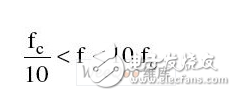
The behavior of the diode is unpredictable, alternating between the flow control inductor and the capacitor. If the frequency is much lower than

The PIN junction of the diode acts as a traditional PN junction. In general, the thicker layer I of the body effect diode allows operation at lower frequencies than the Epi diode.
PIN diode model
Parasitic circuit components (such as harmful inductors and capacitors) are inherent to diode chips and packages, which define switching performance limitations. In the range of the series switch structure, the package capacitance and the chip capacitance (Cp and Cj, respectively) cause the isolation to gradually decrease with increasing frequency. The package parasitic inductance Lp causes the switch insertion loss to increase proportionally with frequency (Figure 1). In order to improve the performance of PIN diodes in the microwave range, manufacturers are constantly creating smaller packages. These packages bring fewer parasitic products. The industry-standard SOT323, SOD-323, and SOD-523 are the proof of the endless drive to make low-cost plastic packaged PIN diode components.
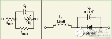
Unfortunately, PIN diodes cannot be modeled in SPICE software commonly used in computer-aided design. SPICE does not establish minority carrier lifetime T-parameters, which is an important parameter for PIN diodes. The PIN diode chip can be modeled as a simple linear circuit consisting of two resistors, a variable resistor, and a capacitor, as shown in Figure 1.
Indoor Full Color LED Display P4 Fixed Install, which using the distribution and modular design to improve the stability of the LED Screen control system. P4 LED Display widely used in Indoor Rental Projects, like Meeting room, Monitoring station, Auditorium, Gymnasium etc etc. Looking forward your cooperation soon! P4 Indoor LED Display is one good choice.
P4 Led Board,P4 Fixed Indoor,Led Board Display,P4 Led Board Display
Shenzhen Jongsun Electronic Technology Co., Ltd. , https://www.jongsunled.com