A text to understand the role and diagram of electronic components
Electronic components are the basis of electronic products. Understanding the types, structures, and performance of commonly used electronic components and correct selection are the basics of learning and mastering electronic technology. Commonly used electronic components are: resistors, capacitors, inductors, potentiometers, transformers, etc. In terms of installation methods, they can be divided into two types: traditional installation (also known as through-hole installation or DIP) and surface installation (also known as SMT). Or SMD). Transistors and diodes are called electronic devices.
1, according to resistance characteristics
Fixed resistors, adjustable resistors, special resistors (sensitive resistors).
Can not be adjusted, we call it a fixed resistance, and can be adjusted, we call it adjustable resistance, common, such as radio volume adjustment, mainly used for voltage distribution, we call it potentiometer.
2, according to the manufacturing materials
Carbon film resistors, metal film resistors, wirewound resistors, Czech resistors, thin film resistors, etc.
3, according to the installation method
Plug-in resistor, chip resistor.
4, by function
Load resistance, sampling resistor, shunt resistor, protection resistor, etc., the main parameters of the resistor:
a. Nominal resistance: The nominal value of the resistor on the resistor is called the nominal value. Unit: Ω, kΩ, MΩ. The nominal values ​​are marked according to the series of standards established by the state, and are not arbitrarily calibrated by the manufacturer. Not all resistance resistors are present.
b. Allowable error: The maximum allowable deviation range of the actual resistance of the resistor for the nominal value is called the allowable error. Error codes: F, G, J, K... (common error ranges are: 0.01%, 0.05%, 0.1%, 0.5%, 0.25%, 1%, 2%, 5%, etc.).
c. Rated power: refers to the allowable power consumption on the resistor under the specified ambient temperature, assuming that the ambient air does not circulate, in the long-term continuous operation without damage or substantially without changing the performance of the resistor. 16W, 1/8W, 1/4W, 1/2W, 1W, 2W, 5W, 10W...
a. Correctly select the resistance and error of the resistor
b. Pay attention to the limit parameters of the resistor
c. The preferred general-purpose resistor
d. According to the characteristics of the circuit
e. Select the resistor according to the board size
Electronic components and diagrams 1, resistors and capacitors(1) Resistor
We wire the battery, switch and bulb into the circuit of Figure 3-1. After the switch is closed, the current flows from the positive pole of the battery, and flows into the negative pole of the battery through the switch and the small bulb, and the small bulb emits light. Both the wire and the small bulb are electrically conductive and they are called conductors. In general, metals are conductors. When the current passes, the conductor has a certain hindrance to the current. This blocking effect is called resistance. The literal symbol for the resistor is R. The basic unit of resistance is ohms (symbol Ω), as well as larger units of kiloohms (KΩ), and megohms (MΩ). Their conversion relationship is:
1MΩ=10^3KΩ1KΩ=10^3Ω
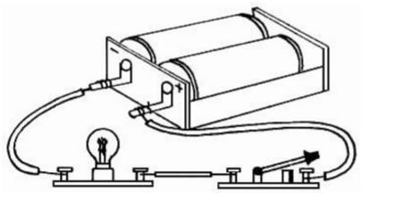
Figure 3-1 Lighting circuit
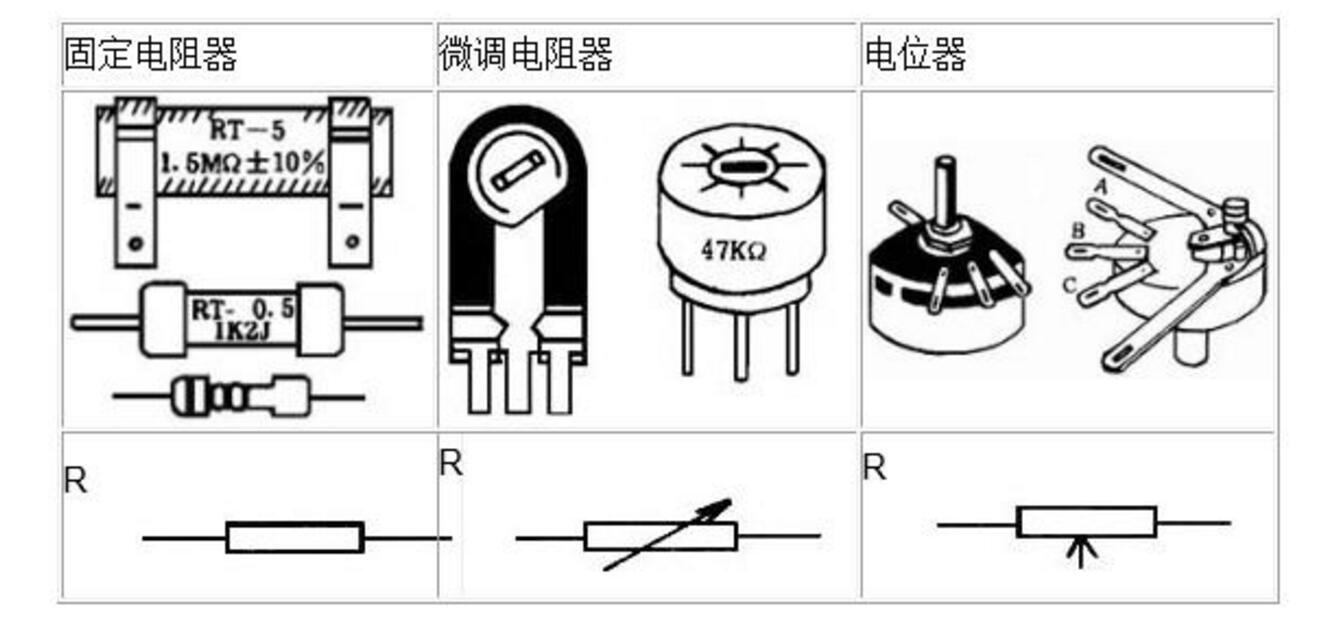
Commonly used resistors fall into two broad categories. A resistor with a fixed resistance is called a fixed resistor. Resistors with continuously variable resistance are called variable resistors (including emblem resistors and potentiometers). Their shapes and graphical symbols are shown in Table 3-1.
Resistors can also be classified into carbon film resistors, metal film resistors or wirewound resistors, etc. due to different materials.
What does the resistor do in the circuit?
Table 1 common resistors
We replaced the switch in Figure 3-1 with a 470 ohm potentiometer (Figure 3-2(A)). Rotate the handle of the potentiometer, the brightness of the small bulb changes with the value of the resistance. The larger the resistance value, the darker the small bulb. This shows that the resistor can control the strength of the current in the circuit. We can refer to this circuit to make a small table lamp that can be dimmed.
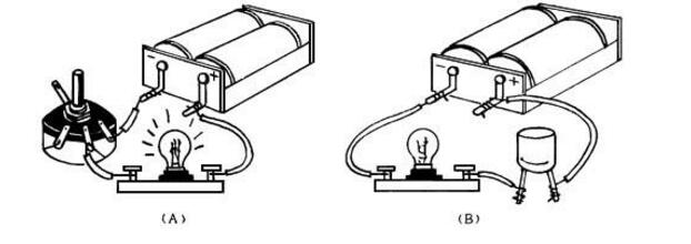
Figure 3-2 The role of resistors and capacitors in the circuit
There are two main parameters of the resistor:
1. Nominal resistance and tolerance.
The value of the resistance marked on the resistor is called the nominal resistance. Such as 1.5K, 5.1Ω...... Its actual resistance allows a certain error, called tolerance, divided into I (±5%), II (±10%), and III (±20%). If the resistor is marked "3KΩI", it means that the resistance of this resistor is 3KΩ, and the error is 5%.
The nominal value and error of the resistor can also be represented by a color circle. Four colorful circular rings are printed on the resistor, three color rings next to the left end of the resistor indicate the resistance value, and the last color ring indicates the tolerance. The identification method is shown in Table 3-2.
The nominal value of the trimmer resistor and potentiometer is its maximum resistance. For example, a 100K potentiometer indicates that its resistance can vary continuously from zero to 100 kΩ.
2. rated power.
Refers to the maximum power allowed while the resistor is operating normally. Above this value, the resistor will burn out due to the heat of distribution. In the electronic production involved in this chapter, if there is no special requirement, the resistors use 1/8w carbon film resistors.
(2) Capacitors
Two conductors that are insulated from each other and close to each other constitute a capacitor. The two conductors are called the two poles of the capacitor and are respectively led out by wires. The character symbol of the capacitor is C. Its size is measured in terms of capacitance. The basic unit of capacitance is Farah (indicated by F), and there are smaller unit microfarads (μF) and picofarads (PF). The conversion relationship of these three units is:
1F=106μF 1μF=106PF
Table two color circle representation 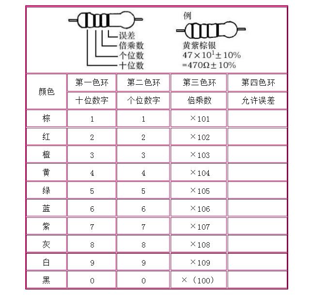
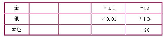
Capacitors can also be classified into fixed capacitors and variable capacitors depending on whether their capacitance can be changed. (including trimmer capacitors and variable capacitors) can also be divided into ceramic capacitors, electrolytic capacitors, air capacitors, etc., depending on the material being fabricated. The shape and shape of the capacitor are shown in Table 3-3.
What is the role of the capacitor in the circuit?
We replace the switch in the circuit of Figure 3-1 with a capacitor (Figure 3-2(B)). When the circuit is turned on, we see that the small light bulb is no longer lit after it flashes. This is because the capacitor has a current in the circuit at the moment of charging. The charging process is quickly over, and after the capacitor is full of charge, the current disappears. The smaller the capacitor capacity, the shorter the time it takes to charge, and the DC current cannot pass through the capacitor. If the power is changed to AC power, the small bulb will continue to emit light. If the AC frequency can be changed, then at the same voltage, the high frequency AC lower frequency AC is easier to make the small bulb brighter through the same capacitor. These experiments can explain that the capacitor is in the circuit, and can function as “DC-blocking, AC-passing†and “passing high-frequency, blocking low-frequencyâ€.
There are also two main parameters of the capacitor:
1. Nominal capacitance and tolerance. Nominal capacitance refers to the capacitance indicated on the capacitor. The allowable error is divided into three levels, which is the same as the representation of the resistor error. Trimmer capacitors and variable capacitors mark the minimum and maximum values ​​of their capacitance, such as 7/270P
2. Withstand voltage. Refers to the highest voltage allowed on the capacitor when the capacitor is operating normally. Do not exceed, otherwise the capacitor will be damaged. In particular, it is necessary to point out that the two poles of the electrolytic capacitor have positive and negative points. They are polar capacitors. When used, they must be connected according to the circuit requirements. The two pins cannot be reversed.
Skill training to recognize resistors and capacitors
Objective To recognize resistors and capacitors and learn to identify the resistance and error of color ring resistance.
Different sizes and types of resistors and capacitors. 10 different color ring resistors.
step
1. Recognize resistors of different sizes and types, and read the nominal resistance and error of the resistors.
2. Recognize capacitors of different sizes and types, and read the nominal capacitance and error of the capacitor.
3. Insert 10 color ring resistors on the cardboard and observe the color of the color ring (refer to Table 3-2), and write the nominal value and error of each resistor.
4. The students asked each other to check, 10 color ring resistors, how many of you identified correctly?
Second, transistors and integrated circuitsTransistors and integrated circuits are often used in electronic production. Transistors are divided into crystal diodes and transistor transistors, which are made of semiconductor materials, so they are also called semiconductor tubes.
(1) Crystal Diode
The text symbol of the crystal diode is VD, and its shape and graphic symbol are shown in Table 3-4.
Table 4 common diodes 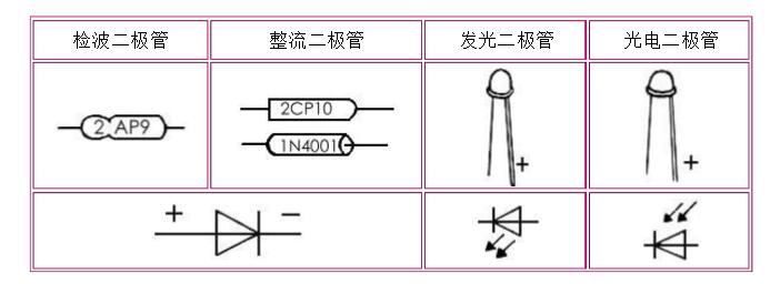
What is the role of a crystal diode in a circuit?
We connect the crystal diode to the switch position in the circuit of Figure 3-1 (Figure 3-3(A)). The light bulb illuminates, indicating that the diode is turned on and the resistance of the diode (called the forward resistance) is small. If the diode poles are reversed (as shown in Figure 3-3(B)), the small bulb will not light up. At this time, the resistance of the diode (called the reverse resistance) is large, and there is almost no current in the circuit. This phenomenon indicates that the diode has a unidirectional conductivity. Using this characteristic of the diode, diodes can be used for detection and rectification.
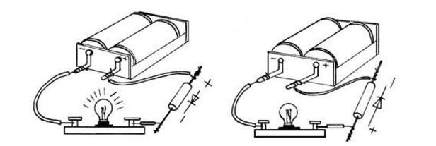
Figure 3 Unidirectional conductivity of a crystal diode
There are two parameters for the crystal diode:
1. Maximum forward current: The maximum current allowed to pass when the diode is turned on.
2. Maximum reverse voltage: The highest voltage applied to the diode when the diode is turned off.
The above two parameters must not be exceeded in use, otherwise the diode will be damaged.
There are also special-purpose diodes, such as photodiodes, light-emitting diodes, etc., which are also commonly used in electronic production.
(two) crystal triode
The transistor is also made of a semiconductor material, and is classified into two types, PNP type and NPN type, due to different structures. The letter symbol of the triode is V. The shape and graphic symbols of commonly used triodes are shown in Table 3-5.
Table 3-5 Common Triode 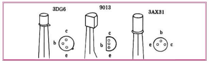
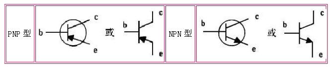
The three poles of the transistor are called base (b), collector (c) and emitter (e). The arrow on the emitter indicates the direction of current flowing through the transistor. It can be seen that the current flow in the two types of triodes is reversed.
The transistor has amplifying and switching effects in the circuit. We use a transistor to amplify the weak signal current in the circuit or make an automatic switch to control the on and off of the appliance.
The working principle of the crystal triode is more complicated and will not be introduced here. The main parameters of the triode are the penetration current and the amplification factor. The smaller the penetration current Iceo, the better the stability of the triode. The magnification β is generally from tens to hundreds, and should be selected according to the needs of the circuit.
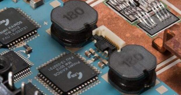
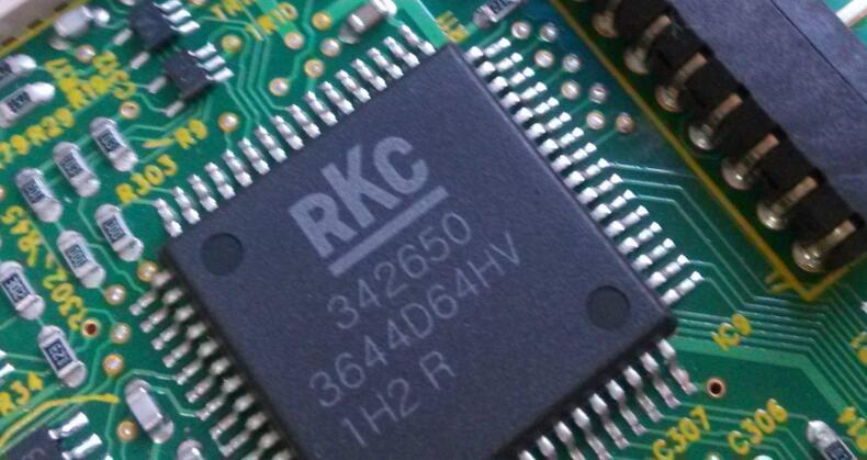
(3) Integrated circuits
In an integrated circuit, components such as diodes, transistors, and resistors and capacitors are fabricated on a small piece of semiconductor material according to the requirements of the circuit structure to form a complete circuit with certain functions, and then packaged. Its text symbol is IC, the shape and graphic symbols of common integrated circuits are shown in Table 3-6.
Table 3-6 Commonly used integrated circuits 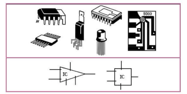
Integrated circuits were developed in the late 1960s with the development of electronic technology. Compared with circuits assembled using discrete components, the integrated circuit has many advantages such as fewer components, lighter weight, smaller size, better performance, and power saving. Therefore, the integration of electronic products has become an inevitable trend in the development of electronic technology.
Shenzhen GEME electronics Co,.Ltd , https://www.gemesz.com