Agricultural picking robot for intelligent robot application case
At present, the research focus of picking robots mostly focuses on the recognition and localization of fruit targets by the visual system. The camera uses the camera to obtain the fruit image information, and through the complex image signal processing algorithm, the program is programmed to logically process the fruit judgment and issue the picking command. This type of robot has better automatic recognition ability, and can be automatically picked, without manual operation. It is the most ideal way for agricultural robots, but the related technologies are not mature enough and the investment is high. This design adopts the human-machine cooperation mode, that is, the artificial identification of the fruit, the robot is responsible for picking. The robot is remotely controlled using a wireless remote control by manual field observation. In this way, the prior art is relatively mature, which shortens the robot development cycle and low cost. Although it can not completely replace human labor, it can reduce the labor intensity of human beings, and can be better popularized for the current level of Chinese agriculture.
In view of the above problems, this paper designs an analog picking robot based on ATmega32, which can realize manual mechanical picking. The infrared arm is used to control the mechanical arm to extend the end gripper to the position of the target fruit, and the grabbing work is completed. Picking tasks.
1 Robot overall design
The robot design incorporates mechanical manufacturing techniques, electronic circuit technology, automatic control and sensor detection technology, and software development programming. In this paper, the sensor of the robot and the infrared remote control are input to the main control board. After the main control board processes, the robot that controls the three-degree-of-freedom robot arm and the crawler chassis structure is output, and the infrared remote control robot arm realizes the grasping of the fruit. The block diagram of the robot is shown in Figure 1.
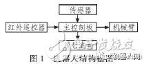
The control mode of the robot is that the wireless control robot adopts a direct manipulation mode, and the operator sends a manipulation command to the remote end through the remote controller. Control the forward movement of the body of the robot, the left and right steering, the movement of the three-degree-of-freedom robot arm, and the rotation, tensioning and closing of the gripper. The robot designed in this paper has the characteristics of simple structure, rich functions and strong expandability.
2 Mechanical device design
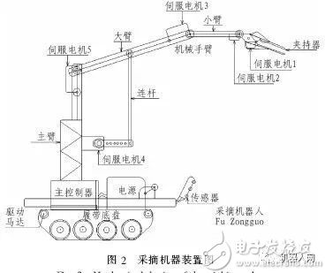
The mechanical drawing of the remote picking robot is shown in Figure 2. It mainly consists of two parts: a two-degree-of-freedom moving carrier and a three-degree-of-freedom with a gripper. The main body of the robot is assembled into a robot body using mesh aluminum material and engineering plastics. The structure is light and convenient, and it is convenient to add modules on the vehicle body. The mobile carrier is a crawler type chassis, and is equipped with a main control circuit board, a picking auxiliary device, various sensors, and a power module. The crawler chassis is double tracked on each side and is driven by four FAULHABER motors. The robot arm is fixed on the crawler type traveling mechanism. The servo motor on the arm uses the MG995 metal gear steering gear with a torque of 10 kg/cm. The servo motor 1 on the arm controls the opening and merging of the gripper, so that the gripper can Complete tasks such as picking and cutting. The servo motor 2 controls the left and right rotation of the gripper. The servo motor 3 controls the arm to move up and down, and the servo motor 4 jointly drives the boom up and down through the link and the servo motor 5.
3 hardware circuit design
Since the robot needs to process a large number of sensor input data while controlling many motors, this imposes stringent requirements on the microcontroller. Based on openness, reliability, real-time and other aspects, this design uses a high-performance AVR processor--ATmega series, and selects the chip model as ATmega32 16AU as the control core. The ATmega32 16AU, with 44 Pins, is an 8-bit high-performance, low-power microcontroller with 32KB of in-system programmable Flash. ATmega32 is a low power 8-bit CMOS microcontroller based on an enhanced AVR RISC architecture.
ATmega32's data throughput rate is up to 1 MIPS/MHz, which can alleviate the contradiction between power consumption and processing speed. Its core has a rich instruction set and 32 general working registers. All registers are directly connected to the arithmetic logic unit (ALU), allowing one instruction to simultaneously access two independent registers in one clock cycle. It has an advanced RISC architecture, 131 instructions, most of the instruction execution time is a single clock cycle, 32 8-bit general-purpose working registers, fully static operation, operating at 16 MHz, performance up to 16 MIPS, only 2 clock cycles Hardware multiplier.
3.1 Control board design
Based on the ATmega32 motherboard circuit consists of power module, crystal module, communication module, motor drive module, remote control coding module and input and output parts. The motherboard circuit is designed with 8 input interfaces, 8 output interfaces, 4 DC motor output interfaces, ISP interface and program download interface, IR infrared remote control receiver access port and IR infrared remote control channel setting dial switch, each module The interface is pluggable, which facilitates the use and function expansion of various modules. The input interface uses a variety of sensors, and the detection signal is input into the MCU. Use the AVR development software on your computer, write the program, and download the program to ATmega32. The infrared transmitting module sends a control signal to the infrared receiving module, and the signal is processed and transmitted to the MCU through the infrared receiving module, and the external sensor module processes the sensing signal into the MCU, and processes and analyzes various input signals to execute the device. Send a control signal.
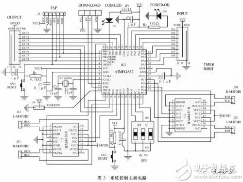
The control board of this design has strong expandability, and can be used for various robot development and intelligent circuit production by adding modules and modifying programs, and is widely used. The control circuit is shown in Figure 3.
3.2 USB to UART download circuit
Serial communication between the AVR and the PC, the motherboard download port uses the UART serial communication method, and the computer cannot be directly connected to the UART port, so a USB to UART converter is required. Based on comprehensive practicality and reliability, the design conversion circuit chip is a single-chip bridge CP2101. The integrated USB transceiver on the CP2101 requires no external resistors, the integrated clock does not require an external oscillator, the integrated 512-byte EEPROM is used to store the product, and the on-chip voltage regulator is 3.3 V output.
3.3 Infrared remote control design
The infrared remote control of this design adopts the BL35P12 chip of Shanghai Belling. The BL35P12 is an OTP type low-power 8-bit general-purpose microcontroller (MCU), which completes the scanning of the keys and the generation of the infrared coded signal. Now it is precisely controlled, so this is adopted. The chip acts as a remote control main control chip. By operating the direction keys to control the robot's front, back, left and right movements, the numeric and special keys can be operated to achieve different actions.
4 software programming
The software design of the picking robot control system mainly considers the control accuracy and the openness of the system. With the programming environment of AVR Studio4, AVRStudio4 is a complete development tool, including editing and simulation functions. With this tool, the source code can be edited. Run on an AVR device. The control software of the picking robot system is composed of a main program, a servo motor driving subroutine, a remote control receiving terminal program, a sensor processing subroutine, and a DC motor control subroutine.
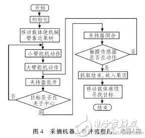
The program is mainly for the processing of AVR microcontroller I / O port, T / C (timer / counter), PWM speed control, interrupt processing and global variables, macro definitions. The program uses structured and modular writing ideas to make the program usable and readable. By calling each subroutine, modify the parameters of the DC motor speed and the angle of the servo motor on the main program, debug to the robot manipulator to the optimal angle, and carry out the software design according to the control strategy. The main program flow chart is shown in Figure 4. .
5 Picking robot debugging and testing
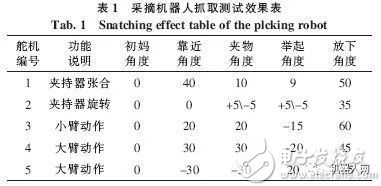
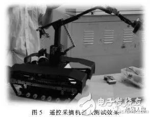
The remote control simulation picking robot designed by this system has a length of 1.2 m and a width of 0.38 m. The maximum speed of the robot is 0.5 m/s and the maximum climbing angle is 45°. The maximum remote control distance of the infrared remote control is 3 m. The robot arm movement is controlled by the steering gear. Here, the mechanical arm steering gear is tested. The steering angles of the servos are shown in Table 1. After the robot assembly test is completed, the physical map test results are shown in Figure 5.
The robot adopts a modular design, each module has complementary functions, and provides a variety of different picking modes, which can be selected according to the working environment. At the same time, the function modules are very scalable and can be expanded by programming. At the same time, multiple tasks can be worked in parallel to improve picking efficiency.
6 Conclusion
In this paper, an ATmega32 picking robot is designed. The main body of the robot uses a sturdy and lightweight material to ensure the robot is light and stable. The robot is driven by a crawler chassis and has an innovative design of a double track strip structure. The picking structure is designed with two or three degrees of freedom mechanical arms, which can flexibly grasp the real objects.
After inputting the control program, the robot can realize semi-autonomous control and infrared remote control through an external sensor. The robot has two kinds of complementary picking modes: vibrating rocking tree and clamping one by one. The actual test shows that this intelligent picking robot can accomplish the expected tasks better. The design system is small and light. Through test and verification, the system has strong human-computer interaction ability, stable and reliable operation, flexible control and rapid response, and achieved the expected design goals. In particular, the movement speed is fast, the movement is sensitive, and it can adapt to the complex orchard environment. Its rapidity and stability meet the prescribed requirements. The robot has strong expandability, powerful function and low cost, and has certain reference value.
Of course, this is just a kind of exploration design for picking robots, which is far from the actual operation. In the future research work, it is necessary to carry out in-depth research and improvement on the actual situation of the height of the fruit tree and the size and size of the fruit, as well as the fragility of the fruit, according to the actual operation. If full intelligent harvesting is used, machine vision must be added. The video monitoring module is fed to the remote robot platform according to the collected image information to guide the robot operation. The mechanical picking hand should also design a stress sensor to intelligently adjust the opening degree to avoid damage to the fruit.
Fiber Optic Distribution Box,Fiber Optic Breakout Box,Fibre Optic Breakout Box,Fibre Break Out Box
Cixi Dani Plastic Products Co.,Ltd , https://www.danifiberoptic.com