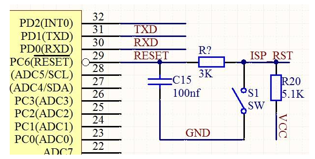
AVR microcontroller reset detection how to identify the reset condition
All I/O registers are set to their initial values ​​when the AVR is reset and the program starts execution from the reset vector. The instruction at the reset vector must be an absolute jump JMP instruction so that the program jumps to the reset processing routine.
The AVR has five reset sources:
Power-on reset. When the power supply voltage falls below the power-on reset threshold VPOT, the MCU resets.
External reset. The MCU resets when the low level on pin RESET is greater than the minimum pulse width.
Watchdog reset. A reset occurs when the watchdog is enabled and the watchdog timer overflows. \

Power-down detection reset. The brown-out detection reset function is enabled and the MCU resets when the power supply voltage is lower than the brownout detection reset threshold VBOT.
JTAG AVR reset. The MCU resets when the reset register is 1.
1. Upper reset
Power-on reset (POR) pulses are generated by an on-chip detection circuit that ensures that the device resets on power-up. The delay counter is triggered after VCC reaches the power-on threshold voltage. Counter overflow
The device remains in reset until it exits. When VCC falls, as long as the detection threshold is below, the RESET signal takes effect immediately.
2. External reset
The external reset is generated by applying a low level to the RESET pin. The reset process is triggered when the reset low level duration is greater than the minimum pulse width, even if no clock signal is running at this time. When the applied signal reaches the reset threshold voltage VRST (rising edge), the tTOUT delay cycle starts. The MCU starts up after the delay expires.
3. Watchdog reset
When the watchdog timer overflows, it will generate a reset pulse with a duration of 1 CK cycle. On the falling edge of the pulse, the delay timer starts counting on tTOUT
4. Brownout detection reset
The switch of the BOD circuit is controlled by the fuse position BODEN. When the BOD is enabled (BODEN is programmed), once VCC drops below the trigger level (VBOT-, Figure 19), the BOD reset is immediately activated. When VCC rises above the trigger level (VBOT+, Figure 19), the delay counter starts counting. Once the overflow time tTOUT is exceeded, the MCU resumes operation.
5.JTAG AVR reset
JTAG resets the register mcur and resets the register to 1 when the MCU resets. The JTAG reset register can be set by the JTAG instruction AVR_RESET and cause the MCU to reset and set JTRF. A power-on reset will clear it, or it can be cleared by writing "0".
6. The MCU Control and Status Register provides information on the reset source that caused the MCU to reset.
The MCU control and status registers provide information about the reset source that caused the MCU to reset.
1.Bit 4 - JTRF: JTAG reset flag
The JTAG reset register can be set by the JTAG instruction AVR_RESET and cause the MCU to reset and cause
2. JTRF is set. A power-on reset will clear it, or it can be cleared by writing "0".
Bit 3 - WDRF: Watchdog Reset Flag
Set when watchdog reset occurs. A power-on reset will clear it, or it can be cleared by writing "0".
3.Bit 2 - BORF: Brown-out Detection Reset Flag
Power-down detection is set when a reset occurs. A power-on reset will clear it, or it can be cleared by writing "0".
4.Bit 1 – EXTRF: External Reset Flag
Set when an external reset occurs. A power-on reset will clear it, or it can be cleared by writing "0".
5.Bit 0 – PORF: Power On Reset Flag
Set on power-on reset. Can only be cleared by writing "0".
In order to use these reset flags to identify the reset condition, the user should read the data of this register as soon as possible and then reset it. If this register is reset before another reset occurs, the subsequent reset source can be checked by checking the reset flag.
In the past 20 years, we have rich experience in design and production standards, won a good reputation at home and abroad. With Casters to customers in North America, Europe, Asia, Australia, South Africa and the Middle East, we experience also let us understand the needs of the international market, fast delivery and safe use. The company has 150 units/sets of production equipment, 2 pouring PU production line, 2 rubber vulcanization production line , 10 sets of large-scale injection molding equipment, automatic welding equipment, equipped with professional level of production to modernize. Using the fully and semi-automatic machinery to achieve excellence in technology and the production of consistency; Research and development team using advanced CAD/CAM software and three-dimensional software design OEM caster; Equipped with professional mold development workshop, by professional engineers to adjust the existing model, constantly updated design, so as to adapt to the changing demands of customers at home and abroad.
we have hard rubber caster wheels,light duty swivel caster,industrial swivel caster,trolley caster,rubber wheels caster.
Wheel Casters,Steel Caster,Gravity Caster,Casters Wheel
BAODING JIMAOTONG IMPORT AND EXPORT CO., LTD , https://www.chinagroundscrew.com