Design and Implementation of Simple Four-Axis Aircraft System Based on STM32
introduction
The quadcopter is a compact, unique flight type vertical take-off and landing aircraft. Compared with ordinary aircraft, it has the advantages of simple structure, low failure rate and greater lift per unit volume. It is used in military and civilian fields. It has broad application prospects and is ideal for performing tasks in tight spaces. Therefore, the quadrotor has a broad application prospect, attracting many researchers and becoming a new research hotspot at home and abroad.
This design mainly realizes a simple four-axis solution by using inertial measurement unit (IMU) attitude acquisition technology, PID motor control algorithm, 2.4G wireless remote communication technology and high-speed hollow cup DC motor drive technology. The design of the whole system includes the flight control part and the remote control part. The flight control part adopts the integrated design of the frame and the control core part to increase the stability of the system. The remote control part adopts the analog joystick operation input to make the operation experience excellent, and the communication between the two parts is adopted. The 2.4G wireless module ensures stable data transmission. The flight control board adopts the high-speed single-chip STM32 as the processor. The motion sensor MPU6050 with three-axis gyroscope and three-axis accelerometer is used as the inertial measurement unit. The communication is communicated through the 2.4G wireless module and the remote control board. Finally, the PWM control method is adopted according to the PID control algorithm. Drive the hollow cup motor to achieve the remote control target.
1, the overall design of the systemThe design of the system hardware mainly consists of two parts: the remote control board and the flight control board. The remote control board adopts the common horn to design the shape of the game controller. The control input adopts the four-way joystick, and the wireless data transmission adopts the 2.4G wireless module. The flight control board adopts a control processing core and a rack-integrated design, that is, the processor and the motor are integrated on the same circuit board, and the conventional size can be used as an accessory of a common toy. The design of the system software also includes the two parts of the remote control board and the flight control board. The design of the remote control board software mainly includes the acquisition of the ADC and the wireless transmission of the data. The software design of the flight control board mainly includes the reception of wireless data, real-time settlement of its own attitude, calculation of motor PID increment and motor drive. The whole four-axis aircraft system includes a human operation remote control end and an aircraft control end. The remote control main controller STM32 collects the joystick data through the ADC peripheral device, and transmits the collected data to the flight control terminal through the 2.4G wireless communication module. The main work of the flight control board is to receive the control signal through the wireless module, and obtain the real-time system acceleration and angular velocity raw data by using the inertial measurement unit, and finally calculate the current system attitude, and then according to the target posture and the attitude of the remote control board. The difference is calculated by the PID motor increment, and then the system is adjusted by the PWM drive motor to achieve stable flight of the aircraft. The overall design block diagram of the system is shown in Figure 1.
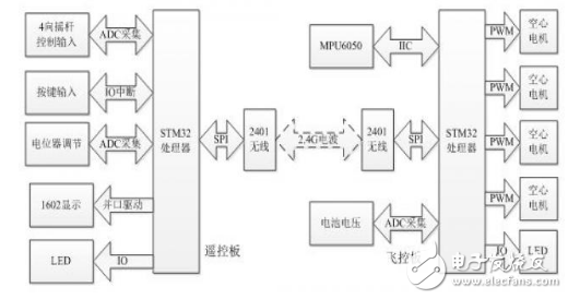
Figure 1 System overall design block diagram
2. Hardware design of four-axis aircraft 2.1 main control unit selectionFrom the perspective of cost and performance, the main control unit of the flight control board and the remote control board are controlled by STMicroelectronics' enhanced high-speed single-chip STM32F103, which is based on the ARM 32-bit Cortex-M3 core architecture. With a frequency of up to 72MHz, it is a microprocessor with a rich resource and high-speed clock. STM32F103 has 64K or 128K bytes of flash program optional memory, up to 20K bytes of SRAM, 2 12-bit A/D converters with up to 16 input channels, 7 channels of DMA controller, up to 80 fast I/ O port, serial single-wire debug (SWD) and JTAG interface debug mode, up to 7 timers, up to 2 I2C interfaces (supports SMBus/PMBus), up to 3 USART interfaces (supports ISO7816 interface, LIN, IrDA Interface and modem control), up to 2 SPI interfaces (18M bit/s), CAN interface (2.0B active), USB2.0 full speed interface. The schematic diagram of the main control unit is shown in Figure 2.
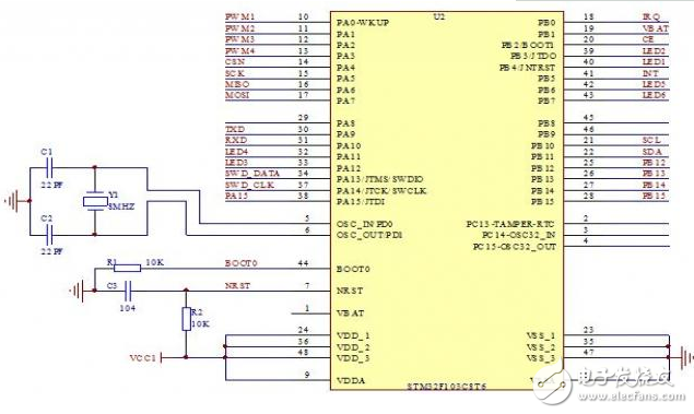
Figure 2 Schematic diagram of the main control unit
2.2 Flight Control Board Circuit DesignThe core design of the flight control board is the design of MPU6050 measurement sensor, NRF2401 wireless module and flight control board motor drive. The inertial measurement unit of the flight control system uses the MPU6050 as the measurement sensor. The MPU6050 is driven by the IIC interface, the clock pin SCL is connected to the PB10 of the STM32, the data pin is connected to the PB11 pin of the STM32, and the data interrupt pin is connected to the PB5. In order to enhance the drive capability, a 10K pull-up resistor is added to each pin. The schematic design is shown in Figure 3.
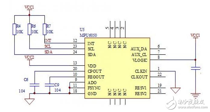
Figure 3 Flight control board inertial measurement unit schematic
Compared with other modules, the electrical system is also an important part. The flight control system uses a 3.7V high discharge rate lithium battery for power supply. The power supply part of the main control chip and the IMU sensor part are powered by independent LDOs, which ensures the stability of the system and the accuracy of the IMU sensor data acquisition. The schematic design of the regulated DC power supply module is shown in Figure 4.
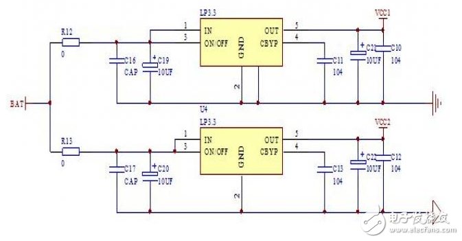
Figure 4 Flight control board power supply voltage regulator schematic
Wall switch and socket ,Champagne wall switch and socket, 16A push switch and socket
Guangdong Shunde Langzhi Trading CO., Ltd , https://www.langzhielectrical.com