Design of Inverter Air Conditioner Controller Based on STM8S208RB
The brushless DC motor has the advantages of simple structure, high efficiency, high power factor, small moment of inertia and low noise. In recent years, the research and application of permanent magnet brushless DC motors have received more and more attention from people, and the country attaches importance to energy conservation and emission reduction. More and more air conditioner manufacturers use brushless DC motors in inverter air conditioner compressors. In the conventional brushless DC motor drive control system, rotor position and speed information are required as feedback signals, and the rotor position and speed are almost obtained by using precision mechanical devices such as photoelectric encoders and resolvers. In the air conditioner compressor, the conventional position sensor is difficult to work normally due to the strong corrosiveness of the refrigerant. Therefore, research on a reliable, low-cost position sensorless control method has become a research on the brushless DC motor controller. One of the hot spots. In this paper, the low-cost, high-performance STM8S208RB microprocessor introduced by ST in recent years is used as the control core. The on-chip AD directly samples the terminal voltage of the non-conducting phase as the detection scheme, which has high cost performance and realizes the inverter air conditioner control. Design of the device.
1 STMicroelectronics STM8S208RB microcontroller introductionSTM8S208RB is a high-performance core microcontroller from STMicroelectronics. It has an enhanced Harvard & CISC architecture, high speed, high processing power, rich on-chip peripherals, easy to use and modular design, and is widely used in brushless DC motors. control. The specific performance indicators of the MCU are as follows: 1) Core: Wide operating voltage of 2.95~5.5 V, working temperature of -40~+125°C, with 3-stage pipeline structure, up to 20 MIPS.2 when working at 24 M crystal frequency Program memory: up to 128 Kbytes of Flash; data can be saved for 20 years at 55 °C after 10 K erasing. Data memory: up to 2 Kbytes of rewritable data memory area eeprom, up to 300,000 erases; RAM: up to 6 Kbytes; 3) Timer: 2 16-bit general-purpose timers, 1 16-bit Advanced control timer with 4 CAPCOM channels, 3 complementary outputs, dead zone insertion and flexible synchronization. 4) 10-bit A/D converter with up to 16 channels, minimum conversion time is 2.33μs.
2 Brushless DC motor without position sensor control technology 2.1 The structure of air conditioning compressor and brushless DC motorIn an air conditioning compressor system using a brushless DC motor, it is mainly composed of three components: a compressor, a motor, and a controller. The motor body of the brushless DC motor is similar to the structure of the permanent magnet synchronous motor. The stator is the armature, the rotor is the permanent magnet, and the use of the rare earth permanent magnet material greatly reduces the weight of the brushless DC motor, simplifies the structure, and improves the structure. The performance, compared with the ordinary DC motor, it removes the mechanical contact structure composed of the commutator and the brush, and adopts the electronic switch reversing device to improve the reliability. When a certain phase of the stator winding of the brushless DC motor is connected with a current, the magnetic field generated by the current interacts with the magnetic field generated by the permanent magnet of the rotor to generate a torque, which drives the rotor to rotate. The magnetic field generated by the conduction sequence of the power switching devices in the driving circuit is synchronized with the rotor rotation angle, thereby functioning as a commutation of the mechanical commutator.
2.2 Mathematical model of brushless DC motorIn the ideal case, the brushless DC motor has a trapezoidal wave back electromotive force with a flat top width of 120°. The motor outputs a square wave voltage or current through an electronic switch and maintains an appropriate phase relationship with the motor back electromotive force, thereby generating an effective electromagnetic torque. The motor is running. At present, the brushless DC motor used mostly adopts a three-phase star-type winding, and operates in two-two-conducting, three-phase six-state mode, as shown in FIG.
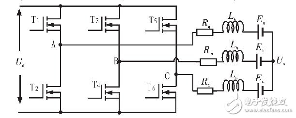
Figure 1 Three-phase inverter bridge circuit
For a permanent magnet brushless DC motor with a winding Y-connection, a three-phase six-state 120° two-two energization mode. Assuming that the three-phase windings of the brushless DC motor are symmetrical, the three-phase voltage equation can be expressed as:
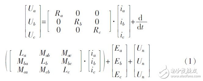
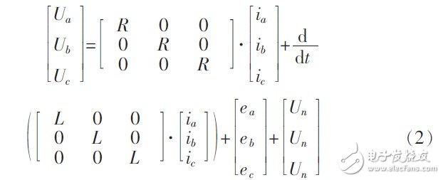
Ua, Ub, Uc motor three-phase winding ground voltage (terminal voltage); ia, ib, ic motor three-phase winding current; Ea, Eb, Ec, motor three-phase winding counter-electric; Ra, Rb, Rc motor Three-phase winding resistance; self-inductance of three-phase windings of La, Lb, and Lc motors; Un is the voltage of the neutral point to ground; Mab is the mutual inductance of the A-phase winding and the B-phase winding, and other similarities. It is assumed from the assumption that Ra = Rb = Rc = R; La = Lb = Lc = Ls; Mab = Mac = Mba = Mbc = Mca = Mcb = M; ia + ib + ic = 0; if L = Ls - M, Substituting the formula, finishing:
The operation of permanent magnet brushless DC motors requires the detection of rotor position signals to achieve commutation. In air conditioning compressor systems, position sensorless technology is often used. The methods without position sensor include back EMF method, magnetoresistance method, flux linkage change method and inductance method. The above various rotor position information detection methods have their own advantages and disadvantages, and it is necessary to comprehensively summarize their advantages and disadvantages according to specific conditions. Program. In view of the high reliability and stability requirements of the air conditioner compressor for the reliability and stability of the brushless DC motor, the detection of the back-zero point method is used to detect the rotor position information in this system. The system adopts two-two conduction, three-phase six-state conduction mode, and the modulation mode is H-PWM-L-ON, that is, the upper arm switch tube is chopped, and the other conduction phase lower arm switch tube is always open.
Set the motor to be in the 120° conduction state: in the PWM "ON" state, T1 and T4 are turned on, as shown in Figure 2. In the PWM "OFF" state, T6 is turned on and T1 is turned off, as shown in Figure 3.
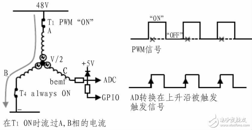
Figure 2 Zero-cross sampling time of the upper arm PWM "ON"
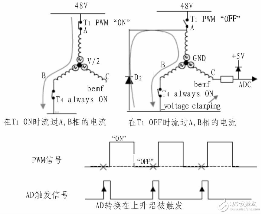
Figure 3 Zero-cross sampling time of the upper arm PWM "OFF"
1) Zero-crossing detection method when PWM is turned on
In the PWM "ON" state, T1 and T4 are turned on. As shown in Figure 2, the three-phase terminal voltage expression is as follows:
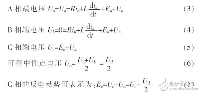
According to the above formula, it is known that when the PWM "ON" is detected, the C-phase terminal voltage is equal to Ud/2, which is the zero-crossing point of the C phase.
2) Zero-crossing detection method when PWM is turned off
In the PWM off state, T1 is turned off and T4 is turned on. At this time, the current flows through the body diode inside T2 as shown in Figure 3.
AB phase terminal voltage Ua=Ub=0 (8)
Phase C voltage Uc=Ec (9)
At this time, the neutral point voltage Un=0; C is opposite to the electromotive force of Ec=Uc; according to the above formula, it is known that when the voltage of the C-phase terminal is 0 when the PWM is "OFF", it is the zero-crossing point of the C-phase. Figure 4 shows the measured voltages of the terminal voltage and zero-crossing in the case of PWM "OFF" and PWM "ON".
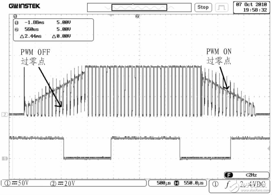
Figure 4 PWM "OFF" and PWM "ON" zero-crossing point measured map
2.4 Fast demagnetization technologyIn order to correctly detect the back-EMF zero-crossing signal, it is necessary to ensure that the power-off phase current decays as soon as possible before the detection, that is, the power-off phase demagnetizes. When controlling the commutation of the brushless DC motor, the current of the power-off phase winding cannot be immediately attenuated to zero due to the inductance of the winding coil. Due to the freewheeling action of the anti-parallel diode, the phase terminal voltage is clamped to 0 V or high voltage. Therefore, the back electromotive force zero-crossing detection cannot be performed during demagnetization. Therefore, the demagnetization process must be accelerated to ensure the stability of the motor. The power-off phase free-wheeling process can be equivalent to the phase inductor being connected in parallel with the voltage source and charging it. Therefore, if a reverse voltage is applied to the shutdown phase at the time of commutation, the demagnetization process can be accelerated. The specific process can be referred to the literature. The experiment found that the use of accelerated demagnetization technology greatly shortened the demagnetization time, improved the accuracy of the back-EMF zero-crossing signal detection, and enhanced the stability of the system operation. The experimental waveforms of the three-phase terminal voltage and zero-crossing point of the brushless DC motor before and after the accelerated demagnetization technique are shown in Fig. 5.
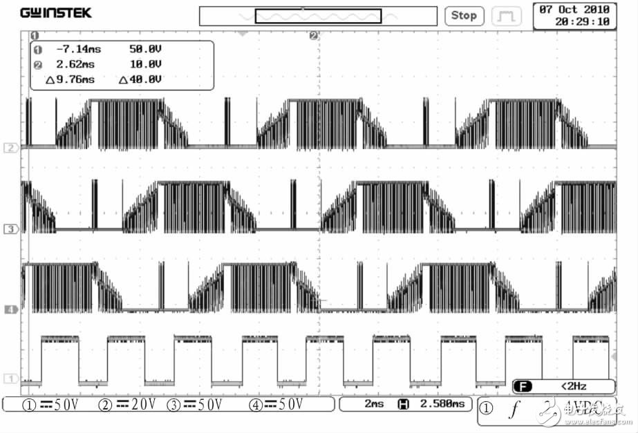
Figure 5 Accelerated demagnetization three-phase terminal voltage and zero-crossing experimental waveform
3 hardware designThe circuit of the inverter air conditioner controller based on STM8S208RB is built, which mainly includes power supply circuit, power drive circuit, overcurrent differential amplifier circuit, zero-crossing detection circuit, etc. (limited to the STM8S208RB minimum system diagram and power supply section).
3.1 drive circuitThe drive circuit is shown in Figure 6. The IR2101 is a cost-effective driver manufactured by IR. It is very simple to use, cost-effective, and can output 100-210 mA. The IR2101 driver can drive a set of power tubes, and the entire power circuit requires only three pieces, which not only saves manufacturing costs, but also improves system stability.
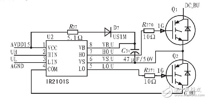
Figure 6 drive circuit
3.2 Overcurrent feedback and overcurrent protection circuitThe current feedback and overcurrent protection monitoring circuit is shown in Figure 7. The current on the bus is 2 milliohms and differentially amplified by 1 mV358. After first-order filtering, the input is input to the STM8S's on-chip AD sampling input. At the same time, this current signal is connected to the comparator Im2903 for the motor. Flow protection detection, when the bus current is too large to set the overcurrent protection threshold, the microprocessor enters the overcurrent protection state.
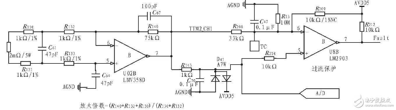
Figure 7 Current feedback and overcurrent protection monitoring circuit
3.3 Zero crossing detection circuitThe zero-crossing detection circuit is shown in the figure below. Figure 8 shows the U-phase zero-crossing detection circuit. PHASE_U is connected to the U-phase of the motor, Z_MS_U is the GPIO control signal of the MCU, ZDtet_U is connected to the AD port of the STM8S, and the transistor Q31 is connected to the AD port. The effect of voltage protection and emitter follow-up increases the input impedance. R91 and D20 play the role of the base accelerating discharge of the triode. When PWM is "ON", Z_MS_U is low level, R92, R93 and R89 form a voltage dividing circuit. When PWM is "OFF", Z_MS_U is high impedance, R89 Does not work, the motor back EMF signal directly enters the AD sampling end through Q31.
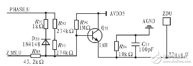
Figure 8 Zero crossing detection circuit
4 experimental environmentA complete 48 V air conditioning compressor system test platform is shown in Figure 9; the system's supply voltage is 48 V, the brushless DC motor is rated at 600 W, and the rated speed is 3,600 rpm. The power device uses IRFB4310.VDSS=100 V of IR Company, Rds(on)=5.6 mΩ, Id=140 A (Tc=25°), Id=97 A (Tc=100°).
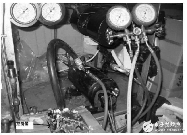
Figure 9 Experimental test platform
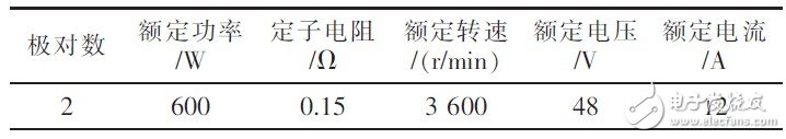
Table 1 Experimental compressor motor parameters
5 ConclusionThe system achieves the stable operation of the brushless DC motor and the goal of no out-of-step commutation by adopting the H-PWM-L-ON modulation method and using the rapid demagnetization technology. The three-stage starting method is used to complete the static start of the brushless DC motor, and the application of the back-EMF detection method in the position sensorless brushless DC motor control system is realized. The experimental results show that the zero-crossing detection method used works well under compressor load.
Tws Sports Headphones,Wireless Sport Earphone,Sports Bluetooth Earphones,Wireless Earphones For Workout
Guangzhou YISON Electron Technology Co., Limited , https://www.yisonearphone.com