Linear regulators use tips to help you troubleshoot low current losses
I replaced a newer and better device with lower current consumption. The result is a malfunction and the new device is even burned. How can I explain this phenomenon?
Linear regulators are fairly simple devices and there are not many challenges. Despite this, occasionally you will have trouble. Next, let us ask Abhinay Patil, the field application manager of ADI's major customers, to explain this problem for everyone -
When I was a field application engineer, sometimes customers would ask me to recommend replacing devices from other vendors. In many cases, the replacement of the device is determined by the customer's production and procurement team, and the original circuit designer may not be aware of the change. The decision-making process is fairly straightforward: the replacement device should have the same functionality, package and pin configuration, and even better electrical specifications than the replaced device. As long as all of these requirements are met, the component engineer is provided with the necessary comparison data to add new components to the bill of materials as a second supplier option. After doing this, you should be done. But in fact, products that work properly with the old device begin to fail on the production line after being replaced with an option. What went wrong?
I was involved in solving such a case. We followed the above process and used an isolated RS-485 transceiver as the second supplier to another vendor's device in the customer's design. The two devices are compatible in shape, size and function, and our devices have better electrical specifications. The customer then placed us a large number of orders for this device and there seems to be no reason to make a mistake. However, the customer reported that the new RS-485 transceiver has failed on the production test bench. Since there are no other changes in the design, the new device in the figure must have gone wrong.
After further investigation, we found that the linear regulator that supplies the bus side of the transceiver is not regulated to 5V as expected, but rises to a higher voltage. We had to double-check and compare the data sheets of the old transceivers and replacements, as well as the data sheet of the linear regulator to determine what went wrong.
“Better†is a qualitative term that depends on the parameters in question. For example, when it comes to speed, CMRR, PSRR, the higher the better; when it comes to offset voltage, drift, the lower the better; and you don't need much engineering knowledge to know that the power consumption is always as low as possible. Is it really? In this particular case, this is not the case. The old transceiver consumes 15 mA (typ) of current on the bus side when idle, while the new device consumes only 2 mA (max). There is no doubt that the new device looks better on the data. Unfortunately, linear regulators seem to be out of order.
Tips
Although linear regulators are fairly simple, there are not many requirements. However, one of its special requirements is that it requires a minimum load current to operate properly. If this demand is not met, the regulator will not regulate properly and the output voltage will be out of range. If the regulator's input voltage is much higher than the desired output voltage, the situation will get worse.
Many modern linear regulators pay special attention to this problem in their design and therefore do not cause malfunctions. Some older devices (such as those used in customer designs in this case) do not take this into account, so additional precautions are required in system design. In some cases, the feedback resistor network of the adjustable output LDO is responsible for the minimum load current.
Unfortunately, if you decide to increase your resistance significantly while maintaining the same ratio, you may be inadvertently in trouble. There is another case where the device powered by the LDO meets the load requirements during normal operation and not in standby mode. These are potential pitfalls to be aware of, so be sure to read the LDO data sheet carefully. If there is a minimum load current requirement, it is usually expressed in some form. Here are a few examples:
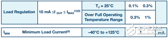
Figure 1. Example of minimum load current in the data sheet
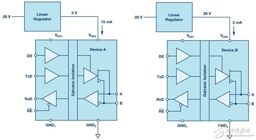
Figure 2. Left-hand wiring diagram: The regulator with the old device works normally (satisfying the minimum load current requirement); the right-hand wiring diagram: the regulator with the new device is unstable (the load current is insufficient)
Going back to our story - once you understand the root cause of the problem, the fix is ​​quite simple. All we have to do is add a bleeder resistor to the regulator output to consume the minimum load current. While irrational customers can easily blame our devices for their problems, the customers in this case have seen a positive side and are excited to learn new technologies from this case.
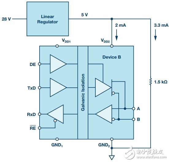
Figure 3. After adding a bleeder resistor to meet the minimum load current requirement, the problem is solved.
Like the perfect ending in a fairy tale - although there is sacrifice, but in the end everyone has lived a happy life.
Solar home energy storage power supply
SHENZHEN CHONDEKUAI TECHNOLOGY CO.LTD , https://www.szfourinone.com