Photoelectric sensor and application circuit
1. The main types of photoelectric sensors can be divided into the following according to the different detection modes:
(1) The reflective photosensor integrates the illuminator and the photosensor, and the light emitted by the illuminator is reflected by the detector to the photosensor.
(2) The transmissive photoelectric sensor places the illuminator and the photosensitive device in opposite positions, and the light beam is also between the two opposite objects, and the detected object passing through the illuminator and the photosensitive device blocks the light beam and starts up. Receiver.
(3) The focusing photoelectric sensor focuses the illuminator and the photosensitive device at a specific distance, and the photosensitive device receives the light beam emitted from the illuminator only when the detected object appears at the focusing point.
1) Using a reflective photoelectric sensor to detect black and white objects using a reflective photoelectric sensor to detect black and white objects
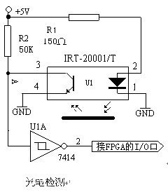
Since the reflection coefficients of the black object and the white object are different, the distance between the reflective photoelectric sensor and the detection object is adjusted, so that the phototransistor can only receive the light beam reflected by the white object. For a black object, because the reflection coefficient is small, the reflected beam is weak, and the phototransistor cannot receive the reflected light. The use of reflected light enables the phototransistor to be turned on and off, thereby enabling resolution of black and white objects.
The working process of the circuit is as follows: When the object to be measured is a black object, the light emitted by the infrared photodiode U1 is reflected weakly, and the phototransistor cannot be turned on, so the point A is high at this time, and the inverter is passed through the inverter. 7414, the signal received by the FPGA or microcontroller is low. When the measured object is a white object, the light emitted by the infrared photodiode U1 is reflected back strongly, and the phototransistor is turned on, so the A point is low at this time, through the inverter 7414, FPGA or microcontroller. The received signal is high; the FPGA or microcontroller detects the level of the input, that is, it can be judged whether the detected object is a white object or a black object.
Integrated photodetector
Integrated Photoelectric Sensors (1) The integrated photoelectric sensors mainly include reflective photoelectric switches, convergent photoelectric switches, transmissive photoelectric switches, reflective plate photoelectric switches, fiber-optic penetrating switches, and fiber-optic reflective switches. The first three.
(2) The working light source used by the working light source mainly has visible red light (650 nm), visible Green Light (510 nm) and infrared light (800-940 nm). Different light sources have their own strengths in specific situations. For example, infrared light has a wide sensitive range without considering the object S***Q, and red or green light is especially suitable for contrast detection. The color of the light source must be based on the color of the measured object. Select, red and red markers should be detected with green light (complementary color).
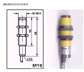
(3) The shape can be divided into: cylindrical cylindrical series, cylindrical series, square series, groove type penetrating series according to the shape of the outer casing. The shape of the more commonly used threaded cylindrical series is shown in Figure 3.6.21.
(4) The wiring diagram is the same as the inductive proximity sensor. Specific models can be found in the relevant website.
Threaded cylindrical photoelectric sensor used in the past to apply the basic principle of detecting black line on the road surface: the light is irradiated onto the road surface and reflected. Because the reflection coefficient of the black line and the white paper is different, it can be judged according to the strength of the received reflected light. line. Using this principle, you can control the path of the car walking. The following possible solutions are designed according to the principle:
Solution 1: The transmission and reception scheme consisting of ordinary light-emitting diodes and photoresistors is shown in Figure 1-1. The working principle: when there is no light, the photoresistor exhibits a high resistance state, and the partial pressure formula shows that the resistor R2 has no voltage drop transistor cutoff, and the collector of the triode outputs a high level; conversely, when there is light, the photoresistor receives To the reflected light, its resistance decreases. By the partial pressure formula, R2 has a voltage drop transistor that conducts and outputs a low level. The high and low levels can be used to determine the shape and direction of the control car. The scheme can achieve basic control requirements, but its shortcoming is that it is easily interfered by external light, and it is not easy to control the behavior of the trolley, which damages the effect of signal acquisition. The main reason is that the reflection effect of visible light directly affects the detection effect in relation to the flatness of the surface and the reflection of the material.

1-1 transmitting and receiving scheme composed of light-emitting diode and photoresistor
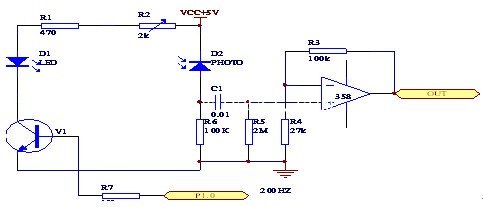
Scheme 2: Pulse-modulated reflective infrared emission receiver. Due to the use of the modulated signal with the AC component, the side can greatly reduce external interference; in addition, the maximum operating current of the infrared transmitting and receiving tube depends on the average current. If a modulated signal with a small duty cycle is used and the average current is constant, the instantaneous current is large (50 to 100 mA), which greatly improves the signal-to-noise ratio. And its response is sensitive, and the peripheral circuits are also very simple. As shown in Figure 1-2. Its advantage is that the interference of external light is eliminated, the sensitivity is improved, and the production is relatively simple.
The 1-2 pulse modulated reflective infrared transmission receiving scheme is known from the above two schemes. Option 2 is more advantageous than solution 1. Many infrared viewpoint probes on the market are based on this principle. The circuit is simple, reliable, and stable in performance. So as to avoid the complexity of the circuit, so I first use the second program as the monitoring system of the car.
2. Motor selection There are many types of small voltage DC motors on the market, which are very convenient to choose. There are mainly ordinary motors and stepping motors.
Solution 1: Using a stepper motor, a remarkable feature of the stepper motor is its ability to quickly start and stop, which meets the standards we require. If the load does not exceed the dynamic torque value that the stepper motor can provide, the stepper motor can be started or reversed immediately. Its conversion sensitivity is relatively high. Forward rotation and reverse rotation control are flexible. But the price of stepper motors is more expensive, and the current situation is too far apart.
Option 2: Use a normal DC motor. The DC motor has excellent speed regulation characteristics, and the speed regulation is smooth and convenient. Wide adjustment range; strong overload capability, able to withstand frequent impact loads, enabling frequent stepless rapid start, brake and reverse. Can meet a variety of special operational requirements that are not allowed.
Since ordinary DC motors are suitable for price, easier to purchase, and relatively simple circuits, it is recommended to use a DC motor as a power source.
3. The choice of motor drive scheme 1: The circuit network or digital potentiometer is used to adjust the partial pressure of the motor to achieve the purpose of adjusting the speed. However, the organization network can only have the first extreme speed regulation, and the components of the digital resistor are relatively expensive and may exist in the interference. The main problem is that the resistance of the general motor is relatively small, and the partial pressure not only reduces the efficiency, but also makes it difficult to implement.
Solution 2: The relay is used to control the switching of the motor, and the speed of the trolley is adjusted by controlling the switching speed of the switch. The advantage of this circuit is that the circuit is relatively simple. The disadvantage is that the relay has a long response time, is easy to damage, has a short life and low reliability.
Solution 3: Four high-power transistors are used to form an H-bridge circuit. The four high-power transistors are divided into two groups, which are alternately turned on and off. They are controlled by a single-chip microcomputer to operate in the switching state, thereby controlling the operation of the motor. The control circuit is a widely used circuit because the four high-power transistors operate only in the saturation and cut-off states, the efficiency is very high, and the high-power transistor switches are fast and highly stable.
(1) The reflective photosensor integrates the illuminator and the photosensor, and the light emitted by the illuminator is reflected by the detector to the photosensor.
(2) The transmissive photoelectric sensor places the illuminator and the photosensitive device in opposite positions, and the light beam is also between the two opposite objects, and the detected object passing through the illuminator and the photosensitive device blocks the light beam and starts up. Receiver.
(3) The focusing photoelectric sensor focuses the illuminator and the photosensitive device at a specific distance, and the photosensitive device receives the light beam emitted from the illuminator only when the detected object appears at the focusing point.
1) Using a reflective photoelectric sensor to detect black and white objects using a reflective photoelectric sensor to detect black and white objects
Since the reflection coefficients of the black object and the white object are different, the distance between the reflective photoelectric sensor and the detection object is adjusted, so that the phototransistor can only receive the light beam reflected by the white object. For a black object, because the reflection coefficient is small, the reflected beam is weak, and the phototransistor cannot receive the reflected light. The use of reflected light enables the phototransistor to be turned on and off, thereby enabling resolution of black and white objects.
The working process of the circuit is as follows: When the object to be measured is a black object, the light emitted by the infrared photodiode U1 is reflected weakly, and the phototransistor cannot be turned on, so the point A is high at this time, and the inverter is passed through the inverter. 7414, the signal received by the FPGA or microcontroller is low. When the measured object is a white object, the light emitted by the infrared photodiode U1 is reflected back strongly, and the phototransistor is turned on, so the A point is low at this time, through the inverter 7414, FPGA or microcontroller. The received signal is high; the FPGA or microcontroller detects the level of the input, that is, it can be judged whether the detected object is a white object or a black object.
Integrated photodetector
Integrated Photoelectric Sensors (1) The integrated photoelectric sensors mainly include reflective photoelectric switches, convergent photoelectric switches, transmissive photoelectric switches, reflective plate photoelectric switches, fiber-optic penetrating switches, and fiber-optic reflective switches. The first three.
(2) The working light source used by the working light source mainly has visible red light (650 nm), visible Green Light (510 nm) and infrared light (800-940 nm). Different light sources have their own strengths in specific situations. For example, infrared light has a wide sensitive range without considering the object S***Q, and red or green light is especially suitable for contrast detection. The color of the light source must be based on the color of the measured object. Select, red and red markers should be detected with green light (complementary color).
(3) The shape can be divided into: cylindrical cylindrical series, cylindrical series, square series, groove type penetrating series according to the shape of the outer casing. The shape of the more commonly used threaded cylindrical series is shown in Figure 3.6.21.
(4) The wiring diagram is the same as the inductive proximity sensor. Specific models can be found in the relevant website.
Threaded cylindrical photoelectric sensor used in the past to apply the basic principle of detecting black line on the road surface: the light is irradiated onto the road surface and reflected. Because the reflection coefficient of the black line and the white paper is different, it can be judged according to the strength of the received reflected light. line. Using this principle, you can control the path of the car walking. The following possible solutions are designed according to the principle:
Solution 1: The transmission and reception scheme consisting of ordinary light-emitting diodes and photoresistors is shown in Figure 1-1. The working principle: when there is no light, the photoresistor exhibits a high resistance state, and the partial pressure formula shows that the resistor R2 has no voltage drop transistor cutoff, and the collector of the triode outputs a high level; conversely, when there is light, the photoresistor receives To the reflected light, its resistance decreases. By the partial pressure formula, R2 has a voltage drop transistor that conducts and outputs a low level. The high and low levels can be used to determine the shape and direction of the control car. The scheme can achieve basic control requirements, but its shortcoming is that it is easily interfered by external light, and it is not easy to control the behavior of the trolley, which damages the effect of signal acquisition. The main reason is that the reflection effect of visible light directly affects the detection effect in relation to the flatness of the surface and the reflection of the material.
1-1 transmitting and receiving scheme composed of light-emitting diode and photoresistor
Scheme 2: Pulse-modulated reflective infrared emission receiver. Due to the use of the modulated signal with the AC component, the side can greatly reduce external interference; in addition, the maximum operating current of the infrared transmitting and receiving tube depends on the average current. If a modulated signal with a small duty cycle is used and the average current is constant, the instantaneous current is large (50 to 100 mA), which greatly improves the signal-to-noise ratio. And its response is sensitive, and the peripheral circuits are also very simple. As shown in Figure 1-2. Its advantage is that the interference of external light is eliminated, the sensitivity is improved, and the production is relatively simple.
The 1-2 pulse modulated reflective infrared transmission receiving scheme is known from the above two schemes. Option 2 is more advantageous than solution 1. Many infrared viewpoint probes on the market are based on this principle. The circuit is simple, reliable, and stable in performance. So as to avoid the complexity of the circuit, so I first use the second program as the monitoring system of the car.
2. Motor selection There are many types of small voltage DC motors on the market, which are very convenient to choose. There are mainly ordinary motors and stepping motors.
Solution 1: Using a stepper motor, a remarkable feature of the stepper motor is its ability to quickly start and stop, which meets the standards we require. If the load does not exceed the dynamic torque value that the stepper motor can provide, the stepper motor can be started or reversed immediately. Its conversion sensitivity is relatively high. Forward rotation and reverse rotation control are flexible. But the price of stepper motors is more expensive, and the current situation is too far apart.
Option 2: Use a normal DC motor. The DC motor has excellent speed regulation characteristics, and the speed regulation is smooth and convenient. Wide adjustment range; strong overload capability, able to withstand frequent impact loads, enabling frequent stepless rapid start, brake and reverse. Can meet a variety of special operational requirements that are not allowed.
Since ordinary DC motors are suitable for price, easier to purchase, and relatively simple circuits, it is recommended to use a DC motor as a power source.
3. The choice of motor drive scheme 1: The circuit network or digital potentiometer is used to adjust the partial pressure of the motor to achieve the purpose of adjusting the speed. However, the organization network can only have the first extreme speed regulation, and the components of the digital resistor are relatively expensive and may exist in the interference. The main problem is that the resistance of the general motor is relatively small, and the partial pressure not only reduces the efficiency, but also makes it difficult to implement.
Solution 2: The relay is used to control the switching of the motor, and the speed of the trolley is adjusted by controlling the switching speed of the switch. The advantage of this circuit is that the circuit is relatively simple. The disadvantage is that the relay has a long response time, is easy to damage, has a short life and low reliability.
Solution 3: Four high-power transistors are used to form an H-bridge circuit. The four high-power transistors are divided into two groups, which are alternately turned on and off. They are controlled by a single-chip microcomputer to operate in the switching state, thereby controlling the operation of the motor. The control circuit is a widely used circuit because the four high-power transistors operate only in the saturation and cut-off states, the efficiency is very high, and the high-power transistor switches are fast and highly stable.
Car Screen Protector,Car Center Console Screen Protector,Car Touchscreen Screen Protector
Shenzhen Jianjiantong Technology Co., Ltd. , https://www.jjttpucuttingplotter.com