Sound control delay switch circuit of LM358 application circuit
The LM358 is a dual operational amplifier. The internal includes two independent, high-gain, internal frequency-compensated op amps for single-supply operation with a wide supply voltage range. It is also suitable for dual-supply operation. Under recommended operating conditions, supply current and supply voltage Nothing. Its range of applications includes sense amplifiers, DC gain blocks, and all other single-supply op amps.
The following describes the application circuit of the LM358: a voice-activated delay switch circuit.
The voice-activated delay switch circuit can control the opening or closing of electrical equipment by sound, as well as the delay function.
Circuit composition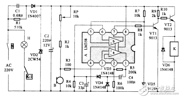
The sound-controlled delay switch circuit made by LM358 is composed of a power supply circuit, a sound signal pickup circuit, an audio signal processing circuit, a driving circuit, a control circuit, and the like as shown in the figure.
The power circuit is composed of a 220V power supply, a switch S, a resistor R1, a step-down capacitor C1, a rectifier diode VD1, a Zener diode VD2, and a filter capacitor C2.
The sound signal pickup circuit is composed of an adjustable potentiometer RP, a resistor RI, and a simple B.
The audio signal processing circuit consists of LM358, resistors R4~R7, capacitors C3 and C4, and diodes VD3~VD5.
The drive circuit consists of resistors R8~R9, transistors VTI and VT2.
The control circuit is composed of an electromagnetic relay K and a diode VD6.
working principle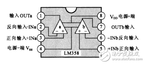
LM358 internal structure diagram
After the voice-controlled delay switch circuit made by LM358 is connected to the 220V AC power supply voltage, the 220V AC voltage is stepped down by the step-down capacitor C1, the rectifier diode VDI is rectified, and the Zener diode VD2 is regulated. After filtering the filter capacitor C2, a low-voltage DC power supply with a negative voltage of about 6V is obtained on C2 for use in a voice-activated switch circuit with LM358 as the core.
In the figure, the LM358 internal op amp a is designed as an amplifier and the op amp b is designed as a voltage comparator. When the voice-activated delay switch is in a silent environment, the microphone B is in a static working state. The integrated circuit LM358 has no audio signal (AC signal) input, and cannot trigger the LM358 internal operational amplifier a. The LM358 has no AC signal on the 1 pin. Output, no signal is sent to pin 6 of LM358 via capacitor C3, diode VD4, the inverting input of voltage comparator b is grounded via resistor R4, biased to low voltage, and the same direction of voltage comparator b The human terminal is biased to 0.7V by resistor R7 and diode VD5, thus controlling the high voltage of the 7-pin output of the LM358C. The forward bias voltage is applied to the triode VT1 via the resistor R8, so that the VT1 is in a saturated conduction state, and the triode VT2 is turned off due to no bias voltage, and the electromagnetic relay K does not operate, wherein the contact switch K-1 is disconnected, and the bulb H is not bright.
When there is a sound, the microphone B converts the sound signal into an audio electric signal, which is sent to the 3 pin of the integrated circuit LM358 via R1, enters the forward input terminal of the operational amplifier a, is amplified by the operational amplifier a, and is output from the a terminal. The LM358's 1 pin outputs an audio AC signal, which is then converted into a high voltage signal by a voltage doubler rectifier circuit composed of C4, VD3, VD4, and C3. It is sent to the reverse input terminal of voltage comparator b by pin 6 of LM358C. Since the R7 and VD5 voltage dividers provide a bias voltage of 0.7V to the non-inverting input of the voltage comparator b through the 5 pin of the LM358C, the output of the comparator amplifier b outputs a low voltage through the 7 pin of the LM358. The triode VTI is turned off due to the absence of the bias voltage, and the triode VT2 is turned on due to the positive bias of the resistors R9 and R10. The electromagnetic relay K is energized to cause the switch K-2 to be engaged, and the bulb H is lit.
In addition, proper selection of the values ​​of capacitor C3 and resistor R4 can keep the high voltage of the 6-pin input of LM358 for a period of time, that is, control the time for extending the lamp. The larger the capacity of the capacitor C3, the larger the resistance of the resistor R4, and the longer the delay time.
If the voice-activated delay switch is installed on the stairs, the person can automatically turn off the lights after walking the stairs.
Circuit component selection
When making the voice-activated delay switch in the picture, A selects the LM358 type dual operational amplifier integrated circuit, which can be integrated with NE532, μPC358C, μPC1251, TA75358P, HA17358, HA17358, GL358, AN1358S, AN6532, MB47358, LA6358, M5223, BA10358 and other models. The circuit is directly replaced. VI1 and VT2 use 9013 type silicon NPN triode. VD1 selects 1N4007 type silicon rectifier diode with reverse voltage withstand voltage of 1000V; VD2 selects 2CW54 type steady voltage diode with voltage regulation value of 6V; VD3~VD6 can select 1N4148 type silicon switch diode for use.
R1 selects RJ-1W type metal film resistor for R1~R10, and RJ-1/8W metal film resistor for R2~R10. RP selects WH5 type small synthetic carbon film adjustable potentiometer. C1 requires the use of CBB-630V polypropylene capacitors, C2, C3, C4 are selected CD11-16 electrolytic capacitors.
B selects CRZ2-113F type electret capacitors for simplicity. K selects 4098 or JZC-22F type small electromagnetic relay with working voltage of 6V.
Post debuggingAfter the sound-controlled delay switch in the figure is produced, the adjustable potentiometer RP should be experimentally adjusted. The adjustment method is: in the case of ordinary sound intensity. The switch does not operate; when there is a louder sound, the voice-activated delay switch can be controlled. Repeated adjustments allow both situations to be considered.
Fridge Temperature Controller,Fridge Controller,Electronics Pcba Refrigerator,Circuit Board Pcba Assembly
Full Industrial CO.,ltd. , https://www.iotaindustrial.com