The core point of the design of the capacitor step-down circuit is here, take away
The working principle of capacitor buck is not complicated. His working principle is to limit the maximum operating current by using the capacitive reactance generated by a capacitor at a certain AC signal frequency.
The conventional method of converting AC mains to low-voltage DC is to use a transformer to reduce voltage and then rectify and filter. When limited by factors such as volume and cost, the simplest and most practical method is to use a capacitor buck power supply.
Pay attention to the following points when using capacitor step-down:
1 Select the appropriate capacitor based on the current of the load and the operating frequency of the AC, not the voltage and power of the load.
2 Current-limiting capacitors must use non-polar capacitors, and electrolytic capacitors must not be used. The capacitor's withstand voltage must be above 400V. The most ideal capacitor is iron-shell oil-immersed capacitor.
3 Capacitor buck cannot be used for high power conditions because it is not safe.
4 Capacitor step-down is not suitable for dynamic load conditions.
5 Similarly, the capacitor step-down is not suitable for capacitive and inductive loads.
6 When DC operation is required, try to use half-wave rectification. Bridge rectification is not recommended. It must meet the conditions of constant load.
Circuit one,
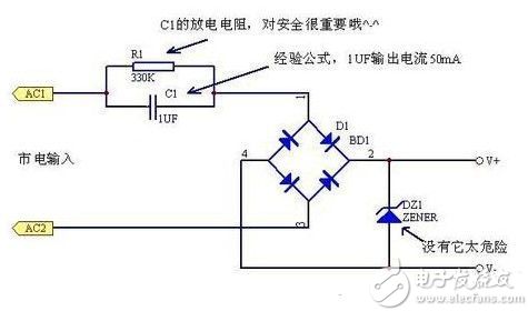
This type of circuit is typically used for low cost non-isolated, low current power supplies. Its output voltage can typically range from a few volts to three tens of volts, depending on the Zener regulator used. The amount of current that can be supplied is proportional to the current limiting capacitor capacity. When using half-wave rectification, the current (average value) can be obtained for each microfarad capacitor: (International Standard Unit)
I(AV)=0.44*V/Zc=0.44*220*2*Pi*f*C
=0.44*220*2*3.14*50*C=30000C
=30000*0.000001=0.03A=30mA
If full-wave rectification is used, double current (average) can be obtained:
I(AV)=0.89*V/Zc=0.89*220*2*Pi*f*C
=0.89*220*2*3.14*50*C=60000C
=60000*0.000001=0.06A=60mA
In general, such circuits have a slightly larger current than full-wave rectification, but because of floating, stability and safety are worse than half-wave rectification, so they are used less.
When using this circuit, you need to pay attention to the following:
1. It is not isolated from 220V AC high voltage. Please pay attention to safety and prevent electric shock!
2, the current limiting capacitor must be connected to the live line, the withstand voltage should be large enough (greater than 400V), and add string anti-surge impact and fuse resistor and discharge resistor.
3. Pay attention to the power consumption of the Zener tube. It is forbidden to disconnect the Zener tube.
Circuit two,
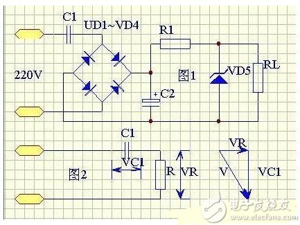
The simplest capacitor step-down DC power supply circuit and its equivalent circuit are shown in Figure 1. C1 is a step-down capacitor, generally 0.33~3.3uF. Assuming C1 = 2uF, its capacitive reactance XCL = 1 / (2PI * fC1) = 1592. Since the on-resistance of the rectifier tube is only a few ohms, the dynamic resistance of the voltage regulator tube VS is about 10 ohms, the current limiting resistor R1 and the load resistor RL are generally 100 to 200, and the filter capacitor is generally 100 uF to 1000 uF, and the capacitive reactance is very Small, can be ignored. If R is used to represent the equivalent resistance of all components except C1, the AC equivalent circuit of the figure can be drawn. At the same time, the condition of XC1>R is satisfied, so the voltage vector can be drawn. Since R is much smaller than XC1, the voltage drop VR on R is much smaller than the voltage drop on C1, so VC1 is approximately equal to the power supply voltage V, that is, VC1=V. According to the electrician principle, the relationship between the average DC current Id after rectification and the average value I of the alternating current is Id=V/XC1. If C1 is in uF, then Id is in milliamp units, and for 22V, 50 hertz alternating current, Id = 0.62C1.
From this, the following two conclusions can be drawn: (1) When the power transformer is used as the rectified power supply, when the parameters in the circuit are determined, the output voltage is constant, and the output current Id changes with the increase or decrease of the load; 2) When using capacitor buck as the rectifier circuit, since Id=0.62C1, it can be seen that Id is proportional to C1, that is, after C1 is determined, the output current Id is constant, and the output DC voltage is different from the load resistance RL. Change within a certain range. The smaller the RL, the lower the output voltage, and the larger the RL, the higher the output voltage. The value of C1 should be selected according to the load current. For example, the load circuit needs 9V working voltage, and the average load current is 75 mA. Since Id=0.62C1, C1=1.2uF can be calculated. Considering the loss of the Zener diode VD5, C1 can take 1.5uF, and the current actually supplied by the power supply is Id=93 mA.
The regulation value of the Zener diode should be equal to the operating voltage of the load circuit, and the selection of the stable current is also very important. Since the capacitor buck power supply provides a constant current, which is approximately a constant current source, it is generally not afraid of load short circuit, but when the load is completely open, the R1 and VD5 circuits will pass all 93 mA current, so the maximum stability of VD5 The current should be 100 mA. Since RL is connected in parallel with VD5, while ensuring RL takes 75 mA of operating current, 18 mA of current is passed through VD5, so the minimum stable current should not exceed 18 mA, otherwise the voltage regulation will be lost.
The value of the current limiting resistor should not be too large, otherwise it will increase the power loss and increase the withstand voltage requirement of C2. If it is R1=100 ohms and the voltage drop across R1 is 9.3V, the loss is 0.86 watts, which can take 100 ohms and 1 watt of resistance.
The filter capacitor generally takes 100 microfarads to 1000 microfarads, but pay attention to its choice of resistance. As mentioned before, the load voltage is 9V, the voltage drop across R1 is 9.3V, and the total buck is 18.3V, considering the stay. There is a certain margin, so it is better to take C2 withstand voltage above 25V.
Circuit three,
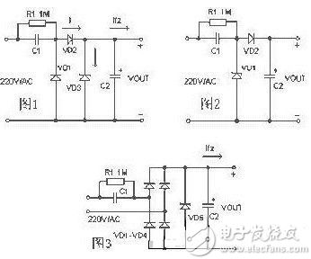
As shown in Figure-1, C1 is a step-down capacitor, D2 is a half-wave rectifier diode, and D1 provides a discharge to C1 during the negative half cycle of the mains supply.
In the loop, D3 is the charge bleeder resistor of C1 after the Zener diode R1 is turned off. The circuit shown in Figure-2 is often used in practical applications. When it is necessary to supply a large current to the load, the bridge rectifier circuit shown in Figure-3 can be used. The unregulated DC voltage after rectification is generally higher than 30 volts, and will fluctuate greatly with the change of load current. This is because the internal resistance of such power supply is very large, so it is not suitable for high current supply. Application.
Device selection
1. When designing the circuit, first determine the exact value of the load current, then refer to the example to select the capacity of the step-down capacitor. Since the current Io supplied to the load through the step-down capacitor C1 is actually the charge and discharge current Ic flowing through C1. The larger the C1 capacity is, the smaller the capacitive reactance Xc is, and the larger the charge and discharge current flowing through C1. When the load current Io is less than the charge and discharge current of C1, the excess current will flow through the Zener diode. If the maximum allowable current Idmax of the Zener diode is less than Ic-Io, the regulator tube will burn out.
2. To ensure that C1 can work *, the withstand voltage should be greater than twice the supply voltage.
3. The bleeder resistor R1 must be selected to vent the charge on C1 for the required time.
Design example
In Figure-2, it is known that C1 is 0.33μF and the AC input is 220V/50Hz. Find the maximum current that the circuit can supply to the load.
The capacitive reactance Xc of C1 in the circuit is:
Xc=1 /(2 πf C)= 1/(2*3.14*50*0.33*10-6)= 9.65K
The charging current (Ic) flowing through capacitor C1 is:
Ic = U / Xc = 220 / 9.65 = 22mA.
Generally, the relationship between the capacity C of the step-down capacitor C1 and the load current Io can be approximated as: C = 14.5 I, where the capacity unit of C is μF, and the unit of Io is A.
Capacitor buck power supply is a non-isolated power supply. In application, special attention should be paid to isolation to prevent electric shock.
The unregulated DC voltage after rectification is generally higher than 30 volts, and it will fluctuate greatly with the change of load current. This is because the internal resistance of such power supply is very large, so it is not suitable for high current supply. Application.
Capacitor buck power supply is a non-isolated power supply. Pay special attention to isolation and prevent electric shock in application.
The working principle of capacitor buck is not complicated. His working principle is to use the capacitive reactance generated by a capacitor at a certain AC signal frequency to limit the maximum operating current. For example, at a power frequency of 50 Hz, a 1 uF capacitor is generated. The capacitive reactance is about 3180 ohms. When an AC voltage of 220V is applied across the capacitor, the maximum current flowing through the capacitor is about 70 mA. Although the current flowing through the capacitor is 70 mA, there is no power consumption on the capacitor. If the capacitor is an ideal capacitor, the current flowing through the capacitor is the imaginary current, and the work it performs is reactive power. According to this feature, if we connect a resistive component in series with a 1uF capacitor, The voltage obtained at both ends of the element and the power it generates are completely dependent on the characteristics of the resistive element.
For example, we connect a 110V/8W bulb in series with a 1uF capacitor. When connected to an AC voltage of 220V/50Hz, the bulb is illuminated and emits normal brightness without being burned. Because of the 110V/8W bulb The required current is 8W/110V=72mA, which is consistent with the current limiting characteristic produced by the 1uF capacitor. Similarly, we can connect the 5W/65V bulb and the 1uF capacitor in series to the 220V/50Hz AC. It will be lit and will not be burned. Because the 5W/65V bulb also has an operating current of about 70mA. Therefore, the capacitor step-down is actually using capacitive reactance current limiting. The capacitor actually acts as a limiting current and dynamic. Assign the role of the capacitor and the voltage across the load.
Elcb Breaker,Elcb Circuit Breaker,Earth Leakage Breaker,Earth Leakage Protection
ZHEJIANG QIANNA ELECTRIC CO.,LTD , https://www.traner-elec.com