Universal board selection and welding methods and techniques
The universal circuit board is a printed circuit board that is covered with a standard IC pitch (2.54mm) and can be inserted and connected as desired. It is commonly called a "hole plate." Compared with professional PCB plate making, the hole plate has the following advantages: low threshold, low cost, convenient use and flexible expansion. For example, in the electronic design competition for college students, the work usually needs to be completed in a few days, so most of the holes are used.
Choice of hole plate
There are two main types of hole plates currently on the market. One type of pad is independent (Fig. 1, hereinafter referred to as a single hole plate), and the other is a plurality of pads connected together (Fig. 2, hereinafter referred to as a perforated plate) ), single-hole plates are divided into single-panel and double-panel. According to the author's experience, the single-hole board is more suitable for digital circuits and single-chip circuits, and the perforated board is more suitable for analog circuits and discrete circuits. Because digital circuits and single-chip circuits are based on chips, the circuits are more regular; analog circuits and discrete circuits are often irregular, and the pins of discrete components often need to be connected to multiple wires. It is convenient. Of course, this is not absolute. Everyone's preferences are different. It is OK to choose to use them more easily.
In addition, the reader needs to distinguish between two different material hole plates: copper plate and tin plate. The copper pad is bare copper, which is golden yellow. It should be stored in a newspaper to prevent the pad from oxidizing. In case the pad is oxidized (the pad is tarnished and not suitable for tin), you can use a cotton swab to rub the alcohol. Clean or wipe with an eraser. The surface of the pad is plated with tin. The pad is silver-white. The substrate of the tin plate is harder than the copper plate and is not easily deformed. Their prices are also different. Take a single panel of 100 cm2 (10cm x 10cm) for example: the price of copper is 3 to 4 yuan, the price of tin is 7 to 8 yuan, and generally not more than 8 cents per square centimeter.
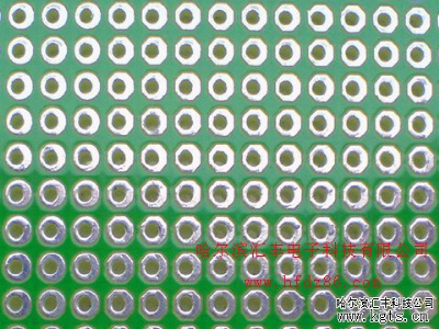
Figure 1 single orifice plate
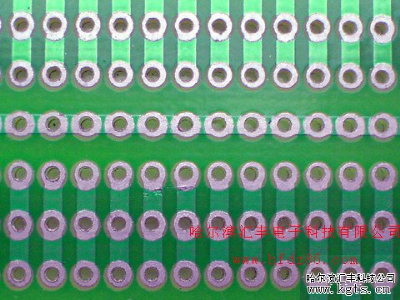
Figure 2 perforated plate
Preparation before welding
You need to prepare enough thin wires (Figure 3) for the wires before soldering the holes. The thin wires are divided into single-strand and multi-strand (Fig. 4): single-strand hard wires can be bent into a fixed shape, and can be used as a jumper after peeling; multiple thin wires are soft in texture and appear to be more welded. Messy.
The hole plate has the characteristics of tight pads, which requires high precision of our soldering iron tip. It is recommended to use a pointed soldering iron with a power of about 30 watts. Similarly, the solder wire should not be too thick. It is recommended to select a wire diameter of 0.5~0.6mm.

Figure 3 Thin wire
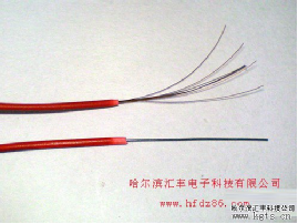
Figure 4 Multi-strand and single-strand fine wire
Welding method of hole plate
For the layout of components on the hole plate, most people are accustomed to "successful", which is based on the key components such as chips, and other components see the stitching method. This method is planned while welding, and the order is in order and the efficiency is high. However, due to the lack of experience of beginners, it is not suitable for this method. Beginners can make a preliminary layout on paper, then draw a pencil on the front of the hole plate (component surface), and then plan the route. Come out and help you solder yourself.
For the welding method of the hole plate, the flying wire connection is generally carried out by using the thin wire mentioned above, and the flying wire connection is not too much skill, but the horizontal and vertical routing are as straight as possible, and the cleaning is clear and clean (Fig. 5). Nowadays, there is a popular method on the Internet called the tin connection method. As shown in Figure 6, the process is good and the performance is stable, but the tin is wasted. Pure tin wiring is difficult, and it is affected by various aspects such as tin wire and personal welding process. If you pull a thin copper wire first and then drag it with a thin copper wire, it is much simpler. The welding method of the hole plate is very flexible, and it varies from person to person to find a method that suits you.
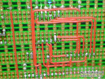
Figure 5 commonly used flying line connection method
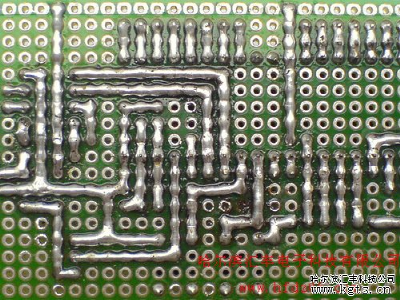
Figure 6 Tin wire method
Welding techniques for hole plates
Many beginners are very unstable and are prone to short circuits or open circuits. In addition to factors such as inadequate layout and poor welders, lack of skill is one of the important reasons for these problems. Mastering some techniques can make the circuit reflect the complexity of the physical hardware greatly, reduce the number of flying lines, and make the circuit more stable. Let's talk about the welding technique of the hole plate in the author's experience.
1. Initially determine the layout of the power and ground lines
The power supply runs through the circuit at all times, and a reasonable power supply layout plays a key role in simplifying the circuit. Some holes are arranged with copper foil running through the entire board. They should be used as power and ground wires. If there is no such copper foil, you need to have a preliminary plan for the layout of the power and ground wires.
2, good at using the components of the pins
The welding of the hole plate requires a large number of jumpers, jumpers, etc., do not rush to cut off the redundant pins of the components, sometimes directly connected to the components of the components to be connected around will be more effective. In addition, in order to save materials, the clipped component leads can be collected as a jumper material.
3, good at setting jumpers
In particular, it is important to emphasize that the addition of jumpers not only simplifies the connection, but also is much more beautiful, as shown in Figure 7.
4, good at using the structure of the component itself
Figure 8 is a matrix keyboard circuit, and Figure 9 is a matrix keyboard soldered by the author. This is a typical example of the use of the structure of the component itself: the light touch button in Figure 9 has 4 feet, two of which are connected, we can use this feature to simplify the connection, the two feet of the electrical connection Jumper. Readers can take a look at Figure 10.
5, good at using pin headers
I like to use pin headers because there are many flexible uses for pin headers. For example, if two boards are connected, the pin header and the row seat can be used, and the pin header serves as a mechanical connection between the two boards and serves as an electrical connection. This draws on the computer's board connection method.
6, cut off the copper foil when needed
When using a perforated plate, in order to make full use of the space, if necessary, a small knife can be used to cut a certain copper foil, so that more components can be placed in a limited space.
7, make full use of the double panel
Double panels are more expensive, and since you choose it you should make the most of it. Each pad of the double panel can be used as a via to flexibly connect the front and back electrical connections.
8, make full use of the space on the board
The components inside the chip holder are both aesthetically pleasing and protect the components (Figure 11).
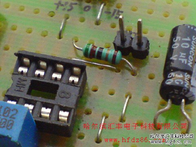
Figure 7 uses more jumpers
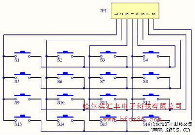
Figure 8 matrix keyboard circuit
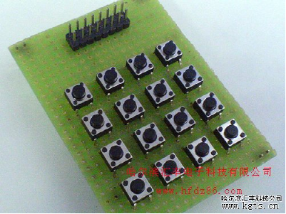
Figure 9 matrix keyboard
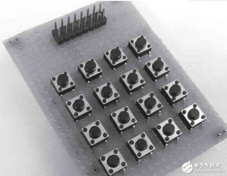
Figure 10 Back of the matrix keyboard
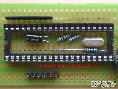
Figure 11 hidden components in the chip holder
The "hole plate" has brought us a lot of convenience, perhaps it has become an indispensable part of your electronic experiment. With reference to the little experience and hands-on practice provided by the author, you will experience better and more suitable methods and techniques.
Barrier Terminal Block
Terminal blocks are used to facilitate the connection of wires. In fact, they are a piece of metal sheet sealed in insulating plastic. There are holes at both ends to insert wires and screws to fasten or loosen them. For example, two wires sometimes need to be connected and sometimes need to be disconnected. At this time, they can be connected with terminals and can be disconnected at any time without having to connect them It's very convenient and fast to weld or wind together. And it is suitable for a large number of wire interconnection. In the power industry, there are special terminal blocks, terminal boxes, all of which are terminal blocks, single-layer, double-layer, current, voltage, common, breakable, etc. A certain crimping area is to ensure reliable contact and enough current.
Barrier Terminal Block
ShenZhen Antenk Electronics Co,Ltd , http://www.coincellholder.com