FSS design analysis for "C/KU band dual-feed satellite communication antenna secondary reflector"
The Cassegrain antenna is flexible in design and can use two or more different band feeds in a single reflector antenna, which saves construction costs. Therefore, multi-feed Cassegrain antennas have been widely used in microwave communication. A key issue in the design of multi-feed Cassegrain antennas is the FSS design used as the secondary reflector of the antenna. With the continuous development of satellite communication, the frequency band of satellite communication is also increasing. The signals of C-band and KU-band can transmit large-capacity signals, while the attenuation of atmospheric particles is small, the most widely used, and now many satellites have this. Two-band transponders use dual-feed Cassegrain antennas for satellite communications, making it possible to use the same antenna for ground stations that implement C/KU band communications. Here, I designed a double-passband FSS with a double-ring unit to be used as a sub-reflecting surface for the C/KU band dual-feed satellite communication antenna (see Figure 1). It transmits C-band satellite communication frequency signals and reflects KU-band satellite signals.
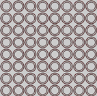
Figure 1 Double ring type frequency selective surface
2 Design principlesThe double-fed Cassegrain antenna design is shown in Figure 2. The main reflection surface is a paraboloid, the secondary reflection surface is a hyperboloid, and the virtual focus of the hyperboloid coincides with the parabolic focus. The phase centers of the two feeds are respectively located at the focal point of the paraboloid and the real focus of the hyperboloid. The secondary reflecting surface is FSS, which can reflect the I-band frequency electromagnetic field and transmit the II-band frequency electromagnetic field. When the I-band frequency electromagnetic field is irradiated onto the main reflecting surface, reflection occurs and is transmitted to the sub-reflecting surface. The electromagnetic field of the frequency is reflected at the FSS. According to the geometric characteristics of the hyperboloid, the electromagnetic wave will be transmitted to the I-band doubly-fed; After the II-band frequency electromagnetic field is irradiated onto the main reflecting surface, reflection occurs and is transmitted to the sub-reflecting surface. The electromagnetic field of this frequency is transmitted at the FSS. According to the geometrical characteristics of the paraboloid, the electromagnetic wave will be transmitted to the II-band doubly-fed.
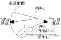
Figure 2 Schematic diagram of the dual feed Cassegrain antenna
The common frequencies of the C-band of satellite communication in China at present are: uplink, 5925MHz~6425MHz; downlink 3700MHz~4200MHz. The common frequency of the KU band is uplink: 14000MHz~14500MHz; downlink 12200MHz~12500MHz, 12500MHz~12750MHz. Therefore, to achieve the dual-feed Cassegrain antenna operating in the C/KU band at the same time, the sub-reflecting surface is required to have a working band transmission and another working band reflection characteristic. Because the FSS design can use the plane FSS to approximate the surface FSS [5], here we only design the plane FSS without designing the hyperboloid FSS. Here we believe that the designed plane FSS transmission characteristics are the same as the surface FSS. Since the antenna sub-reflecting surface is much larger than the FSS unit, we can approximate the designed FSS to infinity when analyzing its transmission reflection characteristics.
3 FSS designThe FSS expected transmission reflection characteristic proposed by the author for "C/KU band dual-feed satellite communication antenna sub-reflection surface" is: the upstream frequency band (5925MHz~6425MHz) in the C-band common satellite frequency (3700MHz~4200MHz) Two transmission passbands with better performance are formed respectively, and a good stopband (12200MHz~12750MHz) is formed in the common satellite frequency of the KU band, so that electromagnetic waves in this frequency band are reflected to meet the application of the KU band and the C-band dual feed. .
Here, using the characteristics of the circular band pass FSS polarization characteristics, the two rings in the unit are used to realize the dual band pass of the uplink working frequency and the downlink operating frequency of the C-band satellite communication. When a double ring is opened in a cell as two bandpass acts, the two rings can be considered as two independent resonators. Although the two rings are coupled to each other, the resonance frequency shifts to the high end, but the two resonance points follow a law proportional to the circumference of the ring. The bandwidth of a single ring-shaped bandpass frequency selective surface is very wide, but the ring resonator (large ring) with a lower resonant frequency is interfered by the small ring resonance frequency at the high frequency of the resonant frequency passband, and the transmission attenuation At the same time, the ring resonator (small ring) with high resonance frequency is interfered by the resonance frequency of the large ring at the low frequency of the resonant frequency passband, and the transmission attenuation decreases rapidly, as shown in Fig. 3. However, the transmission attenuation variation at the frequency band after the resonance point of the single-ring type FSS is much slower than that before the resonance point. In the case of a double ring, if the resonant frequencies of the two rings are far apart, the transmission characteristics of each pass band are similar to those of a single ring FSS. Here, since the broadband transmission of the two transmission attenuations of 4 GHz and 6 GHz is as small as possible, the ring gap of the ring (large ring) having a lower resonance frequency is increased to obtain a wider transmission bandwidth, so that the frequency is 4 GHz. A wider passband band with a smaller transmission attenuation is obtained.
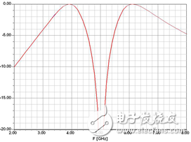
Figure 3 Double-ring FSS transmission curve
The frequency selection surface was analyzed and calculated using the Moment-based method (MOM) simulation software DESIGNER. The frequency selection surface unit structure is designed as shown in Fig. 4. The unit is square arranged, the unit spacing a is 19.7 mm, and a single layer medium and a single layer FSS are selected. Each unit is etched into two rings on the PEC, and the dimensions of each part are R1 = 9.6 mm, R2 = 6.9 mm, W1 = 0.6 mm, W2 = 0.3 mm, dielectric layer thickness d = 1.6 mm, dielectric constant er = 2.65.
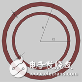
Figure 4 Schematic diagram of the double-ring FSS unit
Figure 5 - Figure 8 show the transmission coefficients of this frequency selective surface when the C-band TE and TM mode electromagnetic waves are incident normally, and the reflection coefficient of the electromagnetic waves in the KU band.
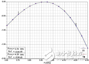
Figure 5: Upstream operating frequency transmission curve of C-band satellite communication
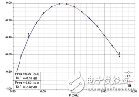
Figure 6: Downstream operating frequency transmission curve of C-band satellite communication

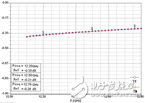
Figure 7: Downstream operating frequency reflection curve of KU-band satellite communication
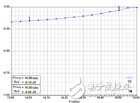
Figure 8: Upstream operating frequency reflection curve of KU-band satellite communication
It can be seen that the transmission loss at the downlink frequency of C700 is 3700MHz~4200MHz is less than -0.84dB; the transmission loss at the upstream frequency of 5925MHz~6425MHz is less than -0.62dB. The reflection attenuation of the electromagnetic field at the common downstream frequency of KU band from 12200MHz to 12750MHz is less than -0.35dB; the reflection attenuation of the uplink frequency from 14000MHz to 14500MHz is less than -0.16dB. Moreover, this FSS has substantially no change in the incident properties of the electromagnetic fields of various polarizations, and substantially no change. Can be applied to a variety of polarization communications.
4 SummaryIn the past, people used the resistance-type FSS when designing the multi-feed Cassegrain antenna sub-reflecting surface FSS. However, due to the wide frequency band of satellite communication, the simple band-stop FSS is difficult to meet the requirements. It is proposed here that the problem is solved by the double-passband type FSS.
Wifi 5 Ceiling Wireless Ap,Wifi Access Point Poe Ceiling Mount,Ceiling Mount Wifi Access Point Home,Access Point Enclosure Ceiling
Shenzhen MovingComm Technology Co., Ltd. , https://www.movingcommiot.com