The design of the software part of the dancing robot: Master microcontroller program and slave program
I. Software Architecture and Communication Protocol
1, software architecture
Before we begin, let's review the software architecture diagram mentioned in the first article.
First of all, introduce the software architecture, the software part of the small π robot mainly contains the mobile phone APP program, the host computer program, the master microcontroller program and the slave program. This week will mainly explain the master microcontroller program and the slave program. The mobile phone APP program and the host computer program will be explained next week. The software architecture of the small π robot is shown in the figure below:
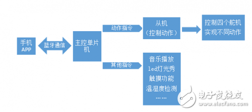
After receiving the data, the master microcontroller determines whether it is an action instruction or other instructions. If it is an action instruction, the instruction is directly sent to the action control single-chip microcomputer, and the action control single-chip microcomputer calls a different array and outputs different PWMs so that the steering gear can be turned through different angles to realize various different actions. If it is other instructions, such as the control of three-color RGB lights, parsing the three-color data, output different voltages, and achieve facial discoloration. For example, speakers can play music in SD cards.
2, communication protocol
In order to facilitate the communication between the mobile phone and the one-chip computer, between the upper computer and the one-chip computer, and between the host and the slave, we have defined our own communication protocol.
The basic format of the communication protocol is:
For example, action instructions. Among them, "" represents the end of the instruction. The meaning of this sentence is to go forward five steps. Other action instructions are similar.
The light color selection instruction consists of three instructions, namely, and. As we all know, red, green, and blue are the three primary colors of light. By controlling the proportions of red, green, and blue, arbitrary color output can be achieved. R, G, and B are the first letters of the English red red, green green, and blue blue, representing red, green, and blue, respectively. The range of R, G, B parameters varies from 0-255, so that more than 16 million colors can be changed.
Second, microcontroller selection
In order to facilitate everyone to write a microcontroller program, we use a completely open source Arduino series microcontroller. Arduino was developed by a European development team for art students in the winter of 2005, so it is relatively simple and easy to use. Arduino consists of hardware (Arduino boards of various models) and software (Arduino IDE). The following picture shows several commonly used Arduino.
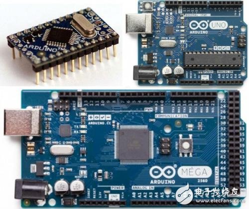
The Arduino IDE runs on three major operating systems: Windows, Macintosh OSX, and Linux. The Arduino language is developed based on the language of wiring. It is the secondary package of the avr-gcc library. It does not require too much MCU basics and programming basis. After simple learning, everyone can quickly develop. Arduino's hardware schematics, circuit diagrams, IDE software, and core library files are all open source. The original design and corresponding code can be arbitrarily modified within the scope of open source protocols.
In short, Arduino has the advantages of cross-platform, simple development and open source, so we use Arduino series MCU.
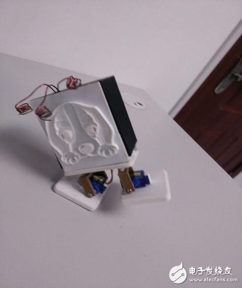
Third, analysis of motion control
The small π robot has 4 degrees of freedom. In other words, the movement of the small π robot is mainly achieved by controlling 4 servos. The four steering gears rotate at different angles in a certain period of time, and then through a certain arrangement and combination, simple movements such as forward, left, right, and back movements, and complicated movements such as shaking heads, lifting feet, shaking legs, and bouncing can be achieved. .
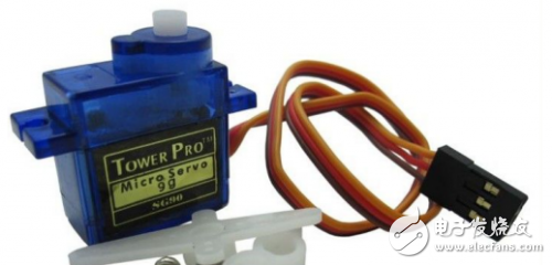
There are three input lines for the servos. The red line is the power line. The black line is the ground line. The servo control signal is a pulse width modulation (PWM) signal with a period of 20 ms, where the pulse width is from 0.5 ms to 2.5 ms, and the position of the rudder is from 0 to 180 degrees, which varies linearly. In other words, to provide it with a certain pulse width, its output shaft will remain at a corresponding angle. No matter how the external torque changes, it will not change the output until it is given a pulse signal with another width. The angle to the new corresponding position. There is a reference circuit inside the servo, which generates a reference signal with a period of 20ms and a width of 1.5ms. There is a comparator that compares the applied signal with the reference signal to determine the direction and size, thereby generating a motor rotation signal.
Because changing the PWM duty cycle too much at a time, the steering gear rotates too fast and the rotation angle is too large, which can cause uncoordinated movements and unattractive behavior. Moreover, the movement of the servo can easily cause the imbalance of the small π robot. Therefore, to control a small π robot to perform a specific action, it is only necessary to control the angle of the servo several times. Each time it rotates only a little angle, the angle of the servo is changed again after a certain time delay. This delay time is generally several milliseconds. This will allow the servo to rotate relatively smoothly.
Fourth, the rest of the hardware part of the program
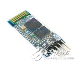
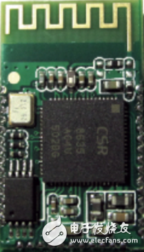
1, Bluetooth module
The Bluetooth module uses the HC-06 and is responsible for communicating with the handset. Communication between the SCM and the Bluetooth module uses serial communication. The baud rate is set to 115200 and the setting code is Serial.begin (115200). Send the command code to Serial.println("").
2, audio playback module
The master control MCU generates a pulse signal to control the Bluetooth audio module by simulating a person pressing a separate key to achieve the function of switching songs, adjusting the volume, playing and pausing.
For example, define the play/pause key as port 2 and the initialization code is:
pinMode(2,OUTPUT);
Generate a pulse signal code:
digitalWrite(2,HIGH) ;//2 is set high
Delay(200);//delay 200 milliseconds
digitalWrite(2,LOW); //port 2 is set to low
Delay(1000);//delay for 1 second
3, colorful LED control
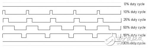
The master microcontroller generates three different PWM signals to achieve the control of the colorful LED, and finally achieve the light show effect.
The PWM signal is a digital square wave where the frequency is constant, but a small fraction of the signal on-time (duty cycle) can vary between 0 and 100%.
4, touch function
The three tentacles use a metal material. When a person touches a tentacles, an interrupt is triggered due to a change in the port level, and a corresponding operation is performed.
The interrupt setting code is as follows:
pinMode(pinInterrupt, INPUT);//Set pin as input
//Enable interrupt pin, interrupt service routine is onChange(), monitor pin change
attachInterrupt(digitalPinToInterrupt(pinInterrupt),onChange,CHANGE);
5. Voice interaction function
The voice is stored in the form of an array on the SD card. Each time voice interaction is performed, the corresponding data is extracted to generate an audio output signal. After filtering, the corresponding voice is played through the speaker.
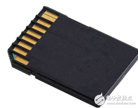
6, SD card module
SD card module read and write can use SPI mode or SDIO mode to read and write data.
The SD library allows reading and writing SD cards, for example on the Arduino Ethernet Shield. The library supports FAT16 and FAT32 file systems on standard SD cards and SDHC cards. It uses a short 8.3 name as a file. The file name passed to the SD library function can contain paths separated by forward slashes, such as "directory/filename.txt". Since the working directory is always the root directory of the SD card, the name refers to the same file, regardless of whether it contains a leading slash (for example, "/file.txt" is equivalent to "file.txt"). Starting with version 1.0, the library supports opening multiple files.
Communication between the microcontroller and the SD card uses SPI, which takes place on digital pins 11, 12 and 13 (on most Arduino boards) or 50, 51 and 52 (Arduino Mega). In addition, another pin must be used to select the SD card. This can be the hardware SS pin - pin 10 (on most Arduino boards) or pin 53 (on Mega) - or another pin specified when calling SD.begin(). Please note that even if you do not use the hardware SS pin, you must leave it as output or the SD library does not work.
The code for these modules is relatively simple and there are plenty of routines on the web. What programs are needed, and everyone is free to combine.
Asic Antminer Machine:Bitmain Antminer E9 (2.4Gh),Bitmain Antminer E3 (190Mh),Bitmain Antminer G2
The latest ETC Ethash Miner of asic antminer machine is Bitmain Antminer E9,it has 2.4gh/s hashrate,It's very profitable
ANTMINER is the world's leading digital currency mining machine manufacturer. Its brand ANTMINER has maintained a long-term technological and market dominance in the industry, with customers covering more than 100 countries and regions. The company has subsidiaries in China, the United States, Singapore, Malaysia, Kazakhstan and other places.
Bitmain Antminer has a unique computing power efficiency ratio technology to provide the global blockchain network with outstanding computing power infrastructure and solutions. Since its establishment in 2013, ANTMINER BTC mining machine single computing power has increased by three orders of magnitude, while computing power efficiency ratio has decreased by two orders of magnitude. Bitmain's vision is to make the digital world a better place for mankind.
Asic Antminer Machine,E9 Etc Miner,E9 Eth Miner,Antminer E9 Eth Miner,antminer ETC Miner
Shenzhen YLHM Technology Co., Ltd. , https://www.hkcryptominer.com