Ultra-utility into eight electronic fault analysis methods
Electronic circuit troubleshooting can generally be detected by input to the input sequence or by the reverse method of output to input. Regardless of the direction from which it is used, electronic circuit fault detection can generally be judged by the following eight methods.
Method 1: Direct observation
When the circuit fails, it is usually not used immediately to measure the instrument. Instead, the naked eye is used to find the abnormal part of the circuit. The direct observation method is divided into no power and power detection.
If the power is not detected, check whether the level and polarity of the power supply voltage meet the circuit requirements; the polarity of the electrolytic capacitor and the pin position of the second and third transistors, and the pin position of the integrated circuit are not the problems of soldering, mis-welding and crossover. Whether the wiring has an unreasonable place; whether the printed board has a broken line when it is printed; the resistor and the capacitor have obvious burning problems.
The power-on inspection is mainly to observe whether the components have overheating, smoke and obvious burnt smell, and whether there is any problem such as high-voltage ignition between the electron tube and the filament of the oscillating tube.
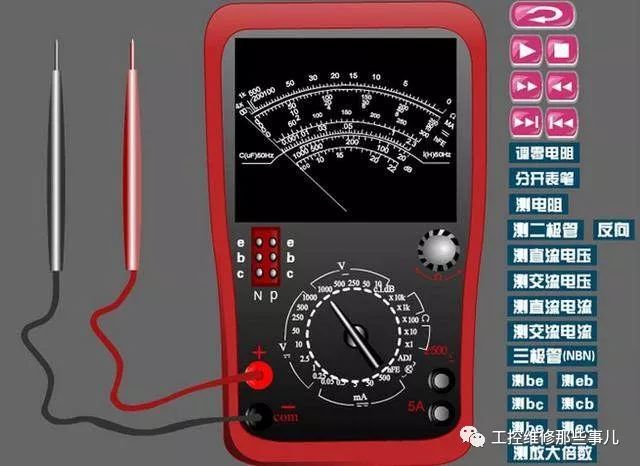
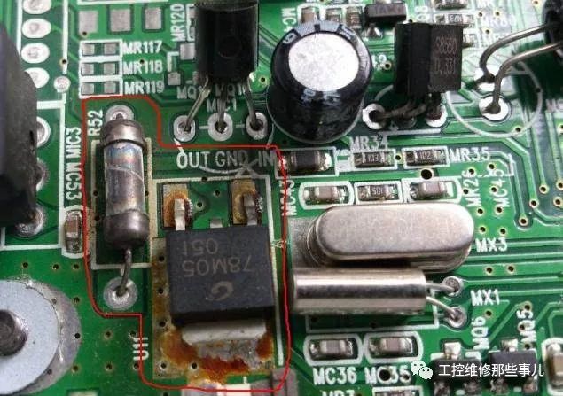
Method 2: Multimeter detection
The multimeter detection is mainly to check the static working point, wherein the power supply system of the electronic circuit, the triode, the integrated block and the resistance value in the line and the DC working state can be detected by a multimeter. Check to see if the value is normal.
Method 3: Signal tracing method
In a complex circuit, you can observe a waveform and amplitude change by inserting a signal at the input and then from the front to the back or from the back to the first level through the oscilloscope.

Method 4: Comparison method
The contrast method is more intuitive, mainly by comparing the parameters of the suspected fault circuit with the same circuit with normal working state, to find out whether there is a value with a large parameter gap, and then analyzing the fault cause, and determining the fault location at the most.
Method 5: Replacement method
For electronic circuits with inconspicuous faults, when it is impossible to make an intuitive judgment or a suspected fault point, the existing identical components can be used for replacement, and the faulty judgment orientation can be shortened by replacing whether the observation circuit is changed.
Method six: bypass inspectionIf there is parasitic oscillation in the circuit, you can use a capacitor of a certain capacity, connect the capacitor between the place to be inspected or the reference grounding point, and then observe whether the oscillation exists. If the oscillation disappears, the oscillation is generated. Stage circuit or nearby circuit. If not, move backwards and continue to look for checkpoints. The choice of capacitors should be careful not to oversize the bypass capacitors, and it is better to eliminate the unfavorable signals.
Method 7: Short circuit inspectionThe short circuit check method is that we actively create a temporary short circuit to make some circuits short circuit. The amplifying circuit shown in the above figure, in which the multimeter measures the collector-to-ground voltage of T2 to be zero. Then we suspect that the L1 circuit has an open circuit, and then make a temporary short circuit at both ends of L1. At this time, if the value of VC2 is normal, the fault is on L1. It should be noted that the short circuit method cannot be used on the power supply circuit.
Method 8: Open circuit inspectionThe short-circuit method mentioned above is used to check the open circuit is the most effective. Similarly, the short-circuit test using the open circuit method is also most effective. The thinking of the open circuit check method is similar to the previous methods, and is used to exclude suspected points and shorten the range. Assume that the regulated power supply is connected to a faulty circuit. At this time, the output circuit is too large. If we turn off a certain branch of the circuit in turn, then observe the current output of the circuit to determine the branch where the fault occurs.
The eight kinds of appeals are actually some of the more common methods. Judging the fault methods is various and can be flexibly applied through different instruments and equipment, so that it is easier to judge complex faults.
| About Paper Covered Wire. |
Paper Covered Wire includes NOMEX Coated Copper Wire, Paper Covered Flat Aluminium Wire, Paper Covered Flat Copper Wire.
Application: oil-immersed transformer windings
Using 100% oxygen free pole as extrusion raw material, insulation material using high density telephone paper, cable paper, polyester, non-woven fabric.Self-locking wrapping is adopted within 6 layers, the bending performance is 15% higher than the national standard, the temperature index is 105℃ after the phone paper and cable paper are impregnated, this product has excellent voltage resistance performance in oil, widely used in transformer coil, stable performance, short processing cycle.

As per Conductor Material:Copper , aluminum
As per Inner Conductor: Paper wrapped bare
Insulation thickness:Double paper covered (DPC) or Triple Paper Covered (TPC) ,According to Customer`s requirements
Insulated Wire Copper,Paper Covered Wire,Paper Covered Copper Flat Wire,Paper Covered Insulated Wire Copper
HENAN HUAYANG ELECTRICAL TECHNOLOGY GROUP CO.,LTD , https://www.huaonwire.com