Fan control system on chip in telecom applications
We have entered the era of electronic product revolution that requires high performance and circuit miniaturization. Improvements in the performance and size of electronic systems have led to increased power consumption and heat dissipation. As a result, thermal management issues arise frequently from different solutions ranging from personal computers to high-end servers. System cooling/thermal management has become a key task for all high performance electronic systems. Forced convection is often used to achieve thermal management. Forced convection improves heat dissipation by diverting air from inside and around the heat source. This can easily be achieved with a brushless DC (BLDC) fan. The speed of such a fan depends on its RMS voltage.
Thermal management can be achieved by running the fan at full speed, but the high speed of the fan can cause the following problems:
â— Improve audible noise
â— increase power consumption
â— Shorten service life (mechanical wear)
â— Increase blockage (dust collection)
However, when the fan is running below the required speed, it will cause insufficient cooling, which will cause the components to overheat. Overheating can cause component failure. In order to solve such problems, the fan speed must be controlled according to environmental conditions (ie, temperature).
The fan speed can be controlled in the following ways:
1. Direct PWM → Pulse width modulation (PWM) can be achieved by increasing or decreasing the pulse width used to control the speed (ie, changing the duty cycle).
2. Linear adjustment → Linear regulator controls the DC voltage of the fan to control the fan speed.
3. DC-DC adjustment → This mode is similar to the linear adjustment, the difference is that the switching regulator is used instead of the linear regulator.
The direct PWM method is more commonly used because of its advantages of low power consumption, low cost, and easy design. Most of the BLDC fans used in thermal management are 4-wire, while some older designs are 3-wire and 2-wire.
4. Line fan
The four wires of this type of BLDC fan are used for power, ground, tachometer output, and PWM input. A typical 4-wire brushless DC fan is shown in Figure 1.
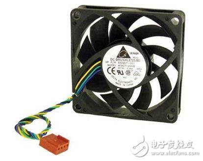
Figure 1: Typical 4-wire DC fan
The 4-wire DC fan contains a Hall effect sensor that senses the rotating magnetic field generated when the rotor rotates. The output of the Hall effect sensor is a pulse train whose period is inversely proportional to the fan speed. The number of pulses generated per revolution depends on the number of fan poles. For the most common 4-pole brushless DC fan, the Hall Effect sensor's tachometer output produces 2 pulses per revolution. If the fan stops rotating due to mechanical or other malfunctions, the tachometer output signal settles to a logic low or high level. This type of fan speed is in revolutions per minute (RPM). The tachometer output of this type of fan is shown in Figure 2.

Figure 2: Fan Tachometer Output
The fans are available in standard sizes, typically 40 mm, 80 mm and 120 mm. When selecting a fan for a cooling application, the most important consideration is the amount of air exhausted by the fan. Exhaust air is typically measured in cubic feet per minute (CFM) or cubic meters per minute (m3/minute). The size, shape, and pitch of the fan blades all affect the amount of air exhausted by the fan. A small fan that excludes the same air for a given time needs to operate at a higher speed than a large fan.
The noise generated by applications that are limited in space and that require smaller fans due to physical size limitations can be significantly enhanced.
To control noise generation, the fan controller can be configured to drive the fan at the lowest possible speed while keeping the operating temperature within safe limits. This approach also extends the life of the fan compared to systems that always run the fan at full speed.
The fan manufacturer specifies the duty cycle and RPM relationship in its data sheet with a tolerance of up to ±20%. To ensure that the fan operates at the expected speed, the system designer needs to run the fan at 20% higher than the rated value to ensure All fans supplied by the manufacturer provide adequate cooling. This can result in excessive noise and increased power consumption.
The fan manufacturer specifies the relationship between the PWM duty cycle and the rated fan speed and displays it via a data point table or diagram. Figure 3 illustrates such information, where the horizontal axis shows the PWM control duty cycle (%) and the vertical axis shows the RPM fan speed.
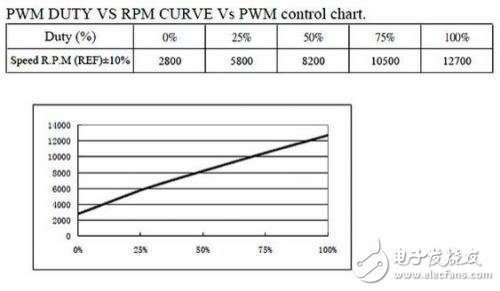
Figure 3: Duty Cycle vs. Speed
It is worth noting that all fans perform inconsistently under the low duty cycle of the PWM pin. Some fans stop spinning when the PWM pin duty cycle approaches 0%, and some fans continue to rotate at this time. In both cases, the duty cycle and RPM relationship may or may not be specified. Similarly, two identical fans may have different speeds at the same duty cycle. When using duty cycle and RPM information, two data points in the linear region that clearly define the fan behavior should be used. As can be seen from Figure 4, the rotational speed is not zero in the case of a PWM duty cycle of zero. Figure 4 additionally illustrates that for a given PWM duty cycle, the same fan has different rotational speeds.
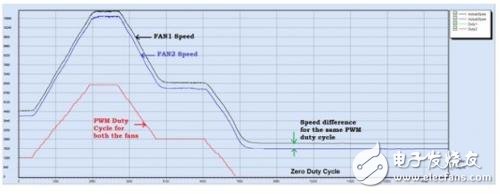
Figure 4: Comparison of the same fan speed and duty cycle
Optical Rotary Sensor,Custom Encoder,Optical Encoder 6Mm Shaft,Handwheel Pulse Generator
Jilin Lander Intelligent Technology Co., Ltd , https://www.jllandertech.com