There are three types of grounding in the low voltage distribution system. Do you know?
The low-voltage distribution grounding system is divided into three types: IT system, TT system, and TN system. These three grounding methods are very easy to confuse. Today I will talk about the principles, characteristics, and scope of application of these three systems, hoping to help the majority of electricians.
First, the definition
According to the current national standard "Low Voltage Distribution Design Specification" (GB50054), there are three types of grounding for low voltage distribution systems, namely IT systems, TT systems, and TN systems.
(1) The first letter represents the relationship between the power source and the ground
The T-power transformer neutral point is directly grounded.
I - The neutral point of the power transformer is not grounded or grounded by high impedance.
(2) The second letter indicates the relationship between the exposed conductive part of the electrical device and the ground
The exposed conductive portion of the T-electrical device is directly grounded. This grounding point is electrically independent of the grounding point on the power supply side.
The exposed conductive portion of the N-Electric device is directly electrically connected to the ground of the power supply.
Second, comprehensive analysis of IT system, TT system and TN system
1, IT system
The IT system is a system in which the neutral point of the power supply is not grounded, and the electrically-conductive device is exposed and the conductive part is directly grounded. The IT system can have a neutral line, but the IEC strongly recommends not to set the neutral line. Because if the neutral line is set, a ground fault will occur at any point of the N line in the IT system and the system will no longer be an IT system.
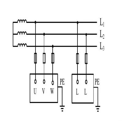
Figure 1 IT system wiring diagram
IT system features:
When the first ground fault occurs in the IT system, it is only the non-faulty relative capacitive current, its value is very small, the exposed conductive part voltage does not exceed 50V, and it is not necessary to immediately cut off the faulty loop to ensure the continuity of the power supply; When the ground fault occurs, the voltage to the ground rises by 1.73 times; the -220V load needs to be equipped with a step-down transformer, or be exclusively supplied by the system external power supply; - install an insulation monitor. Place of use: Higher power continuity requirements, such as emergency power supply, hospital operating room, etc.
The IT mode power supply system has high reliability and good security when the power supply distance is not long. It is generally used in locations where no blackouts are permitted, or places where strict continuous power supply is required, such as electric power steelmaking, operating rooms in large hospitals, and underground mines. The power supply conditions in underground mines are relatively poor and the cables are susceptible to moisture. Using the IT-powered system, even if the neutral point of the power supply is not grounded, once the device is leaking, the relative ground leakage current is still small and will not damage the balance of the power supply voltage. Therefore, it is safer than the neutral grounding system of the power supply. However, if the power supply is used for a long distance, the distributed capacitance of the power supply line to the earth cannot be ignored.
When a short-circuit fault or leakage of the load causes the device case to become live, the leakage current will form a path through the earth and the protection device will not necessarily act, which is dangerous. Only when the power supply distance is not too long is it safer. This type of power supply is rare on the construction site.
2, TT system
The TT system is a system in which the neutral point of the power supply is directly grounded, and the electrically-conductive device is exposed and the conductive part is also directly grounded. The ground of the neutral point of the power supply is usually called the working ground, and the ground of the exposed conductive part of the equipment is called the protective ground.
In the TT system, these two grounds must be independent of each other. Equipment grounding may be that each device has its own independent grounding device, or it may share a grounding device with several devices.

TT system wiring diagram
The main advantages of the TT system are:
(1) It can suppress the overvoltage occurring in the low-voltage power grid when the insulation breakdown between the high-voltage line and the low-voltage line is connected or the high- and low-voltage windings are allocated.
(2) There is a certain leakage capacity for the lightning overvoltage of the low-voltage power grid.
(3) Compared with the non-grounding of the low-voltage electrical enclosure, when the enclosure accident happens to the electrical enclosure, the voltage of the enclosure can be reduced, thereby reducing the degree of damage to the human body.
(4) Because the ground current is large when the single-phase grounding occurs, the protection device (leakage protector) can be reliably operated and the fault can be removed in time.
The main disadvantages of the TT system are:
(1) When lightning strikes on low and high voltage lines, the forward and reverse conversion overvoltages may occur in the distribution transformer.
(2) The protective effect of low-voltage electrical enclosure grounding is less than that of IT systems.
(3) When the metal shell of the electrical equipment is energized (when the phase wire touches the shell or the equipment insulation is damaged and leaks), the grounding protection can greatly reduce the risk of electric shock. However, low-voltage circuit breakers (automatic switches) do not necessarily trip, causing the earth-leakage voltage of the leakage device to be higher than the safe voltage, which is a dangerous voltage.
(4) When the leakage current is relatively small, even a fuse may not be able to be blown, so it is also necessary to protect the leakage protector, so the TT system is difficult to promote.
(5) The TT system grounding device consumes more steel, and it is difficult to recover, time, and materials.
TT system application:
Because the grounding device of the TT system is near the device, the probability of the PE wire breaking is small and it is easy to find.
When the TT system equipment is in normal operation, the shell is not energized. When the fault occurs, the high potential of the shell is not transmitted along the PE line to the entire system. Therefore, the TT system is suitable for supplying power to voltage-sensitive data processing equipment and precision electronic equipment, and has advantages in applications such as explosion and fire hazards.
The TT system can significantly reduce the fault voltage on the leakage equipment, but it cannot generally be reduced to a safe range. Therefore, the TT system must be equipped with a leakage protection device or an over-current protection device, and the former should be prioritized.
The TT system is mainly used for low-voltage users, ie for small users who have not been equipped with distribution transformers and have imported low-voltage power from the outside.
3, TN system
The TN system is the system where the neutral point of the power supply is directly grounded and the exposed part of the equipment is directly electrically connected to the neutral point of the power supply.
In the TN system, the exposed conductive parts of all electrical equipment are connected to the protective line and connected to the ground point of the power supply. This ground point is usually the neutral point of the power distribution system.
The power system of the TN system has one point that is directly grounded. The exposed electrically conductive part of the electrical device is connected to this point through a protective conductor.
The TN system is usually a neutral-grounded three-phase grid system. Its characteristic is that the exposed conductive part of the electrical equipment is directly connected to the grounding point of the system. When a short circuit occurs, the short-circuit current is a closed loop formed by the metal wire. A metallic single-phase short circuit is formed, resulting in a sufficiently large short-circuit current to enable the protective device to act reliably to remove the fault.
If the working zero line N is repeatedly grounded, when the case is short-circuited, a part of the current may be shunted at the repeated ground point, which may cause the protection device to fail to operate reliably or to avoid the failure, thereby expanding the failure.
In the TN system, that is, the three-phase five-wire system, the N-line and the PE-line are separately laid and insulated from each other, and the PE line is connected to the outer shell of the electrical device instead of the N-line. Therefore, the most important thing we care about is the potential of the PE wire, not the potential of the N wire, so repeated grounding is not a repeated grounding of the N wire. If the PE line and N line are grounded together, because the PE line and N line are connected at the repeated grounding point, the line between the repeated grounding point and the working ground point of the distribution transformer has no difference between the PE line and the N line. The original line is the N line. The neutral current that is assumed is shared by the N line and the PE line, and part of the current is shunted through the repeated grounding point. Because it can be considered that there is no PE line on the front side of the repeated grounding point, only the PEN line consisting of the original PE line and N line in parallel, the advantages of the original TN-S system will be lost, so the PE line and N line cannot be Common grounding.
In the TN system, it is divided into TN-S system, TN-C system, and TN-CS system according to whether the protection zero line is separated from the working zero line.
(1), TN-C system
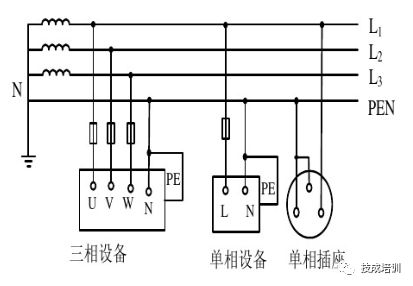
Figure 3 TN-C system wiring diagram
In the TN-C system, the functions of the PE line and the N line are integrated and a conductor called a PEN line simultaneously carries out the functions of both. At the electrical equipment, the PEN line is connected both to the load neutral point and to the exposed electrically conductive part of the device. Due to its inherent technical drawbacks, it has rarely been adopted nowadays, especially in civil power distribution, which basically does not allow the use of TN-C systems.
TN-C system features:
(a) When the device shell is energized, the zero-crossing protection system can increase the leakage current to a short-circuit current. Actually, it is a single phase-to-ground short-circuit fault. The fuse will blow or trip automatically, making the faulty device powered off and safe.
(b) The TN-C system is only applicable to the case of three-phase load balancing. If the three-phase load is unbalanced, there is unbalanced current on the zero line and there is voltage on the ground, so the electrical equipment metal connected to the protection line is The shell has a certain voltage.
(c) If the working zero line breaks, the energized device enclosure protecting the zero is energized.
(d) If the phase of the power supply is earthed, the potential of the enclosure of the device rises, causing the dangerous potential on the midline to spread.
(e) When a residual current circuit breaker is used on a TN-C system main line, all heavy negative ground behind the working zero line must be removed, otherwise the leakage switch will not close, and all repeated ground behind the working zero line must be removed, otherwise the leakage switch Can not close the gate, and the working zero line can not be disconnected under any circumstances. Therefore, in practice, the neutral line can only be grounded repeatedly on the upper side of the residual current circuit breaker.
(2) TN-S system

Figure 4 TN-S system wiring diagram
The neutral line N of the TN-S system is the same as the TT system. Different from the TT system, the exposed electrically conductive part of the electrical equipment is connected to the neutral point of the power supply through the PE wire, and the neutral point is shared with the neutral point of the system, instead of being connected to its own dedicated grounding body, the neutral line (N line). Separate from the protection line (PE line).
The biggest feature of the TN-S system is that after the N line and the PE line are separated from each other at the neutral point of the system, there can no longer be any electrical connection. Once this condition is destroyed, the TN-S system is no longer established.
TN-S system features:
(a) When the system is operating normally, there is no current on the dedicated protection line, but there is an unbalanced current on the zero line. The PE line has no voltage to the ground, so the zero protection of the metal shell of the electrical equipment is connected to the special protection line PE, which is safe and reliable.
(b) The working neutral line is only used as a single-phase lighting load circuit.
(c) The special protection line PE shall not be disconnected, nor shall it enter the leakage switch.
(d) Earth-leakage protectors are used on the main line. Therefore, leakage protectors can also be installed on the TN-S system power supply lines.
(e) The TN-S power supply system is safe and reliable, suitable for low voltage power supply systems such as industrial and civil buildings.
(3) TN-CS System
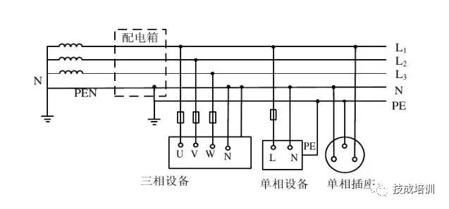
Figure 5 TN-CS system wiring diagram
The TN-CS system is a combination of the TN-C system and the TN-S system. In the TN-CS system, the section from the power source adopts the TN-C system. Because there is no electrical equipment in this section, only the transmission of electrical energy, to a certain point near the power load, separate the EN line to form a separate N line and PE line. From this point on, the system is equivalent to a TN-S system.
TN-CS system features:
(a) The TN-CS system can reduce the voltage of the motor housing to ground, but it cannot completely eliminate this voltage. The magnitude of this voltage depends on the load imbalance and the length of the line. It is required that the load unbalance current should not be too large, and that the PE line should be grounded repeatedly.
(b) The PE wire cannot enter the leakage protector under any circumstances, because the leakage protection device at the end of the line will cause the front leakage protector to trip and cause a large-scale power failure.
(c) In addition to the PE line must be connected to the N line in the general box, the N line and the PE line must not be connected at the other bins, and no switch or fuse should be installed on the PE line.
In fact, the TN-CS system is a variant of the TN-C system. When the three-phase power transformer is in good working ground condition and the three-phase load is relatively balanced, the TN-CS system has a good effect in the practice of construction electricity use. However, in the case of unbalanced three-phase loads and a dedicated power transformer on the construction site, the TN-S power supply system must be used.
Pressure Transducer is a device or device that can sense Pressure signals and convert them into usable output electrical signals according to a certain law.Piezoresistive sensor is an ideal sensor for this purpose. For example, it is used to measure the airflow pressure distribution of the helicopter wing, test the dynamic distortion of the engine air inlet, the pulsating pressure of the cascade and the jitter of the wing. A specially designed silicon pressure sensor is used to measure the central pressure of jet engine, and its working temperature is above 500℃. A silicon pressure sensor with an accuracy of 0.05% is used in Boeing's atmospheric data measurement system. The piezoresistive sensors can be densely installed at the inlet of the wind tunnel and in the model of the engine inlet pipe in the model of the downsized wind tunnel model. The single sensor is only 2.36 mm in diameter and has a natural frequency of up to 300 KHZ, with nonlinearity and hysteresis of ±0.22% of the full range. In biomedicine, piezoresistive sensors are also ideal detection tools. The needle type piezoresistive pressure sensors and sensors which can measure pressure in cardiovascular, intracranial, urethra, uterus and eyeball have been made. Figure 3 is a schematic of a sensor used to measure brain pressure. Piezoresistive sensors are also used effectively in the measurement of explosion pressure and shock wave, vacuum measurement, monitoring and control of the performance of automotive engines, as well as in the measurement of weapons such as gun bore pressure, launch shock wave and other measurements. In addition, piezoresistive sensors are widely used in oil well pressure measurement, direction finding while drilling and detection of fault points of underground sealing cables, as well as flow and liquid level measurement. With the further development of microelectronics and computer, the applications of piezoresistive sensors will develop rapidly
Pressure Measurement Sensor,Resistive Film Foot Sensor,Intelligent Fsr Foot Sensor,Intelligent Pressure Sensor
Dongguan Nanhuang Industry Co., Ltd , https://www.soushine-nanhuang.com